Powell River Project - Foundations for Housing on Reclaimed Mined Lands
ID
460-115 (CSES-218P)
Introduction
The Virginia coal region is faced with unique land-use problems and opportunities. The steeply sloping terrain sharply limits land suitable for economically feasible residential, commercial, and industrial development. Surface mining and mining-related roads and structures affect more than 10 percent of the region’s land area, and subsurface mining affects additional acreages.
Ground conditions in coal-mining regions require special attention when residential development is considered. Today, surface-mining operations can alter landforms through mining and reclamation, thus increasing land suitability for housing and related development. Such “made land,” however, is typically composed of deep soil and rock fills. Such fills undergo long-term settlement under their own heavy weight. Subsurface-mining operations can also affect surface structures by causing land subsidence.
This bulletin summarizes potential problems associated with housing built on recontoured, reclaimed land and suggests methods for dealing with those problems. Special attention is given to the behavior of valley fills and to precautions that should be taken when building in reclaimed areas. Various types of foundations for light structures are considered in relation to their suitability for land that may settle.
Geotechnical Properties of Reclaimed Mined Lands
With care, surface-mining operations in central Appalachia can be conducted to yield reclaimed land that is topographically suitable for residential development. But much of this land will consist of filled land in the form of deep deposits of mining spoil produced by the mining operation. Such fills are almost always deeper than 20 feet and commonly extend to depths of 100 feet or more. Even when carefully placed with compaction, such fills continue to settle under their own weight for many years.
Two basic types of settlement occur; both primarily result from soil particle and rock grain crushing at points of contact. Creep settlement refers to the routine settlement of loose earth materials over time, as these materials consolidate under forces imposed by the weight of materials above. Water saturation reduces rock strength and increases contact crushing, causing collapse settlement, which is technically known as hydroconsolidation because of its association with saturation caused by rising groundwater or percolating surface water. Fill placed in a relatively dry state, as is often the case with rocky mine spoils, induces post-construction settlement likely to consist less of the “creep” and more of the “collapse” variety. Conversely, fill placed wet will undergo considerable creep but less collapse. Thus, for a particular fill, the amount, type, and even the rate of settlement will depend on a variety of factors, including fill depth, moisture and compaction conditions during placement, and ground-water conditions after placement.
Although the amount and rate of creep settlement within a deep fill is difficult to predict without careful soil testing, geotechnical engineers have formulated a few general rules:
- The amount of settlement varies directly with fill depth, so that a 100-foot fill will settle twice as much as a 50-foot fill constructed with similar materials under similar conditions.
- The rate of creep settlement decreases exponentially with time; for example, if it takes one year for 1 inch of settlement, it will take on the order of 10 years for a second inch and 100 years for a third inch. Clearly, early settlement is rapid, but the process slows quickly.
- The settlement amount varies greatly with the degree of compaction during placement. For example, if a deep fill with little compaction was expected to undergo 10 inches of settlement, one would expect this same fill, well compacted, to settle only 1 to 2 inches. Partial compaction would give results between these extremes.
Obviously, one would like to restrict housing to well-compacted, stable fills. These are called “engineered” fills because they are carefully constructed to stringent engineering specifications.
Specifications can be written to build engineered fills, but it is often difficult to achieve these specifications in the field. Running a 20-ton vibratory roller at least six times over a 1-foot layer (“lift”) of soil gives good compaction, but this will be costly in terms of time, fuel, and equipment. On surface mining operations, 1-foot lifts will not generally be economically feasible. Compaction can be achieved economically, however, through the action of haul trucks and other machinery. Four-foot lifts give only partial compaction, which may lead to two to three times as much settlement as “good compaction.” With 2-foot lifts, the nature of the material, vehicle weights and speeds, moisture content, and other variables determine whether or not compaction is adequate to minimize settlement.
Compaction that can hold creep settlement of deep fills to 1 to 2 inches sounds promising. Light structures can easily tolerate this, especially if much of the settlement is uniform rather than differential across the length of the foundation.
Extensive damage has occurred in expensive homes built on carefully engineered valley fill when hydrocon-solidation caused severe settlement soon after construction. In many of these cases, the settlement was induced by rising groundwater within the fill, but there are also cases where houses that had performed well for several years suddenly settled because of percolating water from large plumbing leaks or sudden concentrations of rainwater. Engineers are not entirely surprised by this; they are familiar with the fact that crests of large earth and rock-fill dams, carefully engineered and well compacted to hold back large volumes of water, commonly settle several inches with the first filling of the reservoir. Clearly, for deep valley fills, collapse settlement or hydroconsolidation must be expected.
The results of field observations and laboratory work suggest a few general rules for hydroconsolidation. If compaction is good, only deep fills will settle; hydro-consolidation is unlikely to occur in fills less than 20 feet deep. Also, it is unlikely to occur in fills that were placed while very wet or that became saturated as they were built. But, for deep soil and rock fills placed at optimum moisture content (the moisture content at which compaction is most effective), hydroconsolidation may be both substantial and rapid – even when the fills have been adequately compacted during construction.
There is no easy solution for hydroconsolidation in deep fills. Surface drainage combined with rock underdrain systems may intercept and control rainwater and groundwater, but deep fills generally become wet anyway, no matter how well drained. Thus, hydrocon-solidation must be anticipated. Indeed, the process may be accelerated by water brought by the development itself: for instance, effluent from septic tanks; runoff from gutters, leaders, and paved areas; and flow from plumbing leaks – common in areas of unstable ground. Such water may accelerate the softening of point-to-point rock contacts and collapse settlement of the fill. On the positive side, settlement from hydroconsolida-tion is short term. It ceases in a short period of time so that once a fill has become saturated by groundwater, for example, further settlement is unlikely to occur. Thus, old fills can be expected to be relatively stable.
To summarize: Fills in reclaimed mined land can be placed to minimize post-construction creep settlement, but this requires engineered fill with good compaction, which is uneconomical in most surface-mining situations. Even if good compaction is achieved, settlement from another mechanism, hydroconsolidation, may cause unacceptable surface settlement as the deep, heavily loaded fill becomes wet from groundwater or percolating surface water. Therefore, reclaimed mined lands containing deep fills must be considered to be unstable ground, subject to settlement, except where the fills are old and it is reasonably certain that they have already “aged” and settled. Accordingly, one should keep large settlements of fill in mind when designing residential and other light structures to be placed on recently reclaimed mined land.
Tolerance of Structures to Settlement
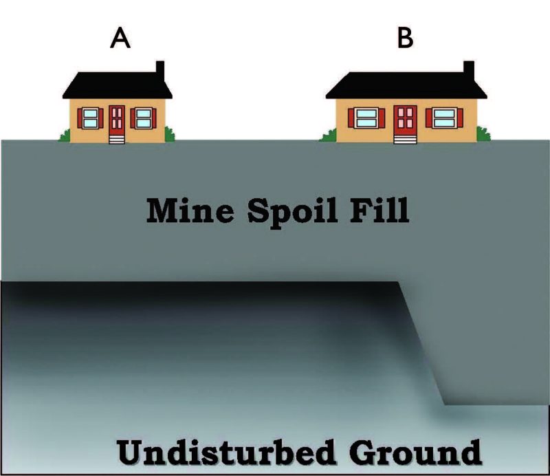
Structures suffer little damage from uniform, even ground settlement. For filled land, however, a large proportion of ground settlement is of the uneven, differential settlement type (i.e., the depth of settlement varies under different parts of the structure; see figure 1). Such settlement leads to damaging structural distortion.
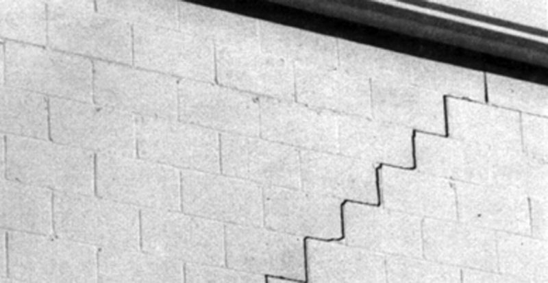
Structural distortion from differential settlement is often described in terms of angular distortion. If the downward movement of a portion of a building is not shared by the rest of the building, angular distortion shows up as “sag” or “hog” in joists or beams and as “lean” or “twist” in studs or columns. As a result, walls are distorted away from a strictly rectangular shape, cracks appear in plaster and masonry (figure 2), door and window openings become distorted, and ultimately, the integrity of the structure can be threatened. Damaging distortion also occurs as simple lateral strain in which the horizontal distance between a building’s corners changes, generally increasing, leading to the opening of joints and cracks. Lateral strain is also associated with settlement, especially deep-seated settlement, and may comprise a significant part of the total structural distortion.
Damage from structural distortion may range from merely cosmetic to severe, depending on the amount of distortion and the type of structure. Many older homes have uneven floors, doorframes out of plumb, and cracks in plaster walls, yet they remain perfectly livable despite the cosmetic damage. However, when distortion prevents doors and windows from properly closing, when masonry walls develop severe cracks and fractures so that maintaining comfortable temperatures within the home becomes a problem, or when the supporting power of load-bearing walls is compromised, damage is serious. Severe structural distortion can pull apart plumbing connections, crack chimney flues, and stress electrical connections, leading to fire hazards. Generally speaking, 1 inch of lateral strain or 2 inches of differential settlement – or some of each – leads to the beginnings of severe damage in a home.
Some structures tolerate distortion better than others. Most homes can absorb slight amounts of distortion with a minimum of damage, but the more rigid a structure or structural component, the less its tolerances. Plaster, for example, can tolerate little distortion without cracking. Stud frames, paneling, and gypsum board can resist distortion better than brick or masonry block. As shown in table 1, frame construction, open floor plans, and truss roofs can be expected to have a high tolerance to differential settlement. Also, mobile and manufactured homes are constructed to withstand distortions beyond those expected for conventional on-site construction, because they must tolerate unusual strains during transportation and placement. Nevertheless, even these homes, if rigidly anchored to settling ground, can be severely damaged.
Structure |
Description |
| Rigid | Precast concrete, concrete block, or unreinforced brick exterior walls; masonry or plaster interior walls; slab-on-grade acts as combined flooring and building support |
| Semi-rigid | Reinforced masonry or brick reinforced with exterior steel-tie bars; window and door openings reinforced to resist angular distortion; slab-on-grade isolated from walls |
| Flexible | Steel or wood framing; exterior siding of brick veneer with articulated joints or pan-els of metal, vinyl, or wood; interior walls of gypsum board or wood-base panels; vertically oriented construction joints; strip windows or metal panels separating rigid wall sections with 25-foot spacing or less, to allow differential movement; all water pipes and drains into structure with flexible connections; suspended floor or slab isolated from wall |
| Split | Walls or rectangular sections move as units (flexible joints at 25-foot spacing or less between units); suspended floor or slab-on-grade isolated from walls (probable cracking of slab accounted for in design); all water pipes and drains into structure with flexible connections
|
Placement of Structures
On reclaimed mine sites that are constructed over level benches, primary settlement is likely to be vertical. On lands constructed over valley fill or other locations where the underlying solid ground has substantial pitch, horizontal movements can also be expected to occur.
Horizontal movements of as much as 50 percent of the maximum vertical movement may occur near the sides of a valley fill. Also, maximum differential movement and structural distortion should be expected closer to the sides than to the centerline of a filled valley. In contrast, little horizontal movement, but maximum vertical movement, can be expected near the fill centerline.
Accordingly, for structures on valley fill, one might expect the least damage in a narrow house near the middle of the fill, with the long axis of the structure parallel to and directly above the former valley’s base. The greatest damage to houses might be expected near the outer edges of the fill, above the former valley’s sideslopes, where the greatest surface distortion and horizontal movement can be expected.
If one chooses to build over valley fill, site development and building construction should be conducted with an understanding of the fill’s physical properties and the likelihood that subsidence processes will cause structural distortion. Such buildings should be only one or – at most – two stories in height and should not have basements. The plan dimension should not exceed 80 feet in length, and the first floor should be on one plane only. The long axis of the building should be parallel to the contour of the original land surface beneath the fill. Separate buildings should be at least 6 feet apart, with breezeways and link structures less than 12 feet in width. Flexible structural systems and elements should be employed, with provision for added clearance in windows and doors to increase tolerance to distortion. For utility connections, flexible joints that can accommodate both rotation and translation should be used.
In general, a valley fill will not constitute an ideal housing site. If one has the choice of placing a building over a valley fill or a reclaimed bench over a mine pit with a level bottom, the bench area will be a better choice. The total depth of fill, the vertical settlement, and the associated horizontal movements are all likely to be less over the bench area.
In geotechnical terms, some of the most favorable mined-land construction sites are located on the level benches produced by the “shoot and shove” mining of the 1950s, 1960s, and early 1970s. However, builders on such sites should assure that the buildings are over the stable bench with a reasonable setback from the outslope, yet are far enough from the highwall so as not to be endangered by falling rock.
The favorable qualities of the older benches come from the fact that depth of fill to solid rock is often less than 20 feet, while the filled material has had many years to settle. Construction difficulties can result from the presence of a filled “outslope” (fill placed on sloping lands beyond and below the level bench). The structure must be firmly and totally supported by the solid bench, and water outflow from the home should be diverted away from the outslope. Just as water can induce col-lapse failure of recently filled lands, the introduction of large quantities of water to an apparently stable outslope can cause movement of the outslope materials. Water-induced slides can result from severe storm events as well as from the activities of a nearby homeowner. If such movement is severe, material that is vertically above the outer edge of the bench area can be within the slide zone. Thus, if housing is to be constructed on an older bench, it is critical to keep the home – and any water outflow from the home – away from steep outslope areas.
Foundation Alternatives
Foundation type has little influence on the amount of settlement, which depends on soil and site conditions. But – depending on how the building is constructed – there can be large differences in the damages caused by a given amount of settlement.
The purpose of a foundation is to provide stable support for the structure and to anchor that structure to resist the force of winds, including uplift. Because cost is a major element of concern to most homebuilders, economy is essential both in site preparation and in substructure (foundation) construction. There are three basic approaches to substructure design for unstable ground:
- Carry the foundation to firm bearing, as with deep piers or piles.
- Provide a substructure sufficiently strong and stiff to resist or bridge potential ground movements.
- Provide flexible or adjustable connections between the foundation elements and the superstructure.
For filled areas of any substantial depth, it is not eco-nomically practical to carry the foundation to firm ground except for expensive, heavy structures such as multistory buildings. This suggests the second approach, which provides a substructure that is strong, stiff, and resistant to distortion, with a superstructure that is relatively flexible so as to allow for large movements without serious damage. This basic approach is commonly applied to areas of expansive soils, where large movements occur upon expansion of swelling clay as it becomes moist. The design and use of adjust-able connections has been employed in areas of per-mafrost soils, compressible fills, and subsidence from underground mining.
Perimeter Wall Foundations
This type of foundation, common for homes through-out the United States, generally consists of a wall foot-ing of cast-in-place concrete containing some steel reinforcement. The purpose for the footing is to pro-vide uniform support for the perimeter walls. Interior posts or columns are placed on individual footings to support interior beams. Anchor bolts and steel anchor straps commonly connect the foundation and the super-structure. Either a basement or a crawl space may be provided.
The perimeter wall foundation is economical both in materials and in construction, but it is poorly suited to unstable ground such as mine fills. There is a great potential for damage from uneven movement in the sub-soil. Fractures may appear in walls after only minimal distortion, or if differential movement exceeds 0.5 inch. Moreover, in the event of fracture, repair or adjustment is difficult. This foundation meets none of the criteria for success on unstable ground; that is, it lacks strength and stiffness and does not allow for flexible or adjust-able connections with the superstructure. Field studies have shown that homes with basements are especially prone to expensive damage in areas of severe settlement. Accordingly, the elimination of basements from construction in settlement-prone areas such as mine fills is strongly recommended.
Stiffened Ground-Slab Foundations
When differential movements between 0.5 inch and 4 inches are expected, a stiffened ground slab is a conventional recommendation. A stiffened slab is constructed in a fashion similar to a conventional concrete slab-on-grade building support. However, recommended thicknesses for stiffened slabs generally exceed those of conventional slabs, thickness is further increased around the edges, and additional ribs of concrete are used to reinforce the slab’s midsection. The entire structure is heavily reinforced with steel.
The philosophy for stiffened slabs is that design must allow for the possibility of only partial ground sup-port for the slab – at times along the edges and at othertimes in the interior. The slab must be able to resist the resulting stresses without excessive deformation. The Department of the Army Technical Manual Foundations in Expansive Soils (1983) is close to the state of the art, and many places have established successful local practices, including design innovations that economize on the use of reinforcing steel and concrete.
Despite such innovations, stiffened slabs cannot be recommended as the answer to problems of residential construction on filled lands. One reason is their expense: They are very costly relative to other foundation types. They are difficult to repair, so if difficulties arise, repair can be justified only for high-cost homes.
Pier or Post-and-Pad Foundations
This type of foundation is commonly used to support older rural homes. Modern piers generally consist of cylindrical cast-in-place concrete extending below the superstructure so as to transfer the building load deep below the surface. Piers may be built with a variety of materials, such as treated timber, and need not extend deeper than below the frost line. For support-ing strength, deep, cast-in-place piers may rely in part on the contact between the soil and the sides of the shaft for frictional resistance, but most piers depend chiefly on end bearing. To increase end-bearing capacity, small spread footings or “pads” may be provided. Thus, the width of the pier only needs to be sufficient to sustain the column load from the structure. This arrangement is economical for light structures, especially when posts of treated timber or built-up masonry are combined with cast-in-place, reinforced concrete pads.
In contrast to perimeter wall footings or slab foundations, piers tend to concentrate the structural load. Thus, soil with a relatively high bearing capacity (such as those soils commonly produced by consolidated mine spoils) must be at hand. Alternatively, piers may be built deep to reach firm bearing (i.e., the undisturbed rock below the mining fill), but cost increases quickly with pier depth. Piers deeper than 8 feet below grade are seldom practical for residential structures. Except in areas of settlement, piers have no particular advantage over the more common perimeter wall foundation.
A major advantage of pier foundations in areas of settlement lies in the accessibility of the foundation elements. If the pier undergoes settlement, an appropriately designed foundation- superstructure connection can be adjusted. Normally, this “design for adjustment” is not the case. Foundations having built-in provision for releveling are called adjustable foundations and are discussed below.
An important cost element in construction using pier or post-and-pad foundations is the need to provide support members (generally beams or girders) spanning the distance between piers.
In the case of perimeter wall foundations, the walls serve this purpose around the exterior of the structure. Interior beams do not have to support large loads; for one- and two-story houses, they usually consist of economical built-up wooden beams supported by columns at 8- to 12-foot intervals. Perimeter beams, however, must be designed for the larger loads imposed by the roof and exterior walls. If this requires steel girders, material and material handling costs greatly increase. Thus, if pier foundations are to be used, economy may dictate single-story frame construction with a light-weight veneer, such as vinyl siding. For settlement-prone areas, an additional benefit of such construction is flexibility.
Adjustable Foundations
The concept of using adjustable foundations for troublesome soil is not new in geotechnical engineering. Structures ranging from a portion of Yankee Stadium to a bank in San Francisco were built on adjustable foundations years ago, with the “adjustment” generally in the form of jacks. It has also proved practical to use adjustable connections in Alaska, where active perma-frost may require periodic releveling of structures.
A five-story, precast concrete building in Pennsylvania was designed by GAI Consultants Inc., using an adjustable pier foundation on deep engineered fill (GAI 1983). The total settlements accommodated were as much as 8 inches, with up to 6 inches of differential settlement between columns. The engineer provided approximately 6 to 8 inches of adjustment capability into each column by providing four permanent, adjust-able column bolts near its base. The columns were then adjusted upward with removable hydraulic flat jacks as needed to prevent excessive differential settlement of the structure. Unfortunately, this innovative design is too expensive for modest structures such as single-family residences, but it does illustrate the principles of successful design against large amounts of settlement in unstable ground.
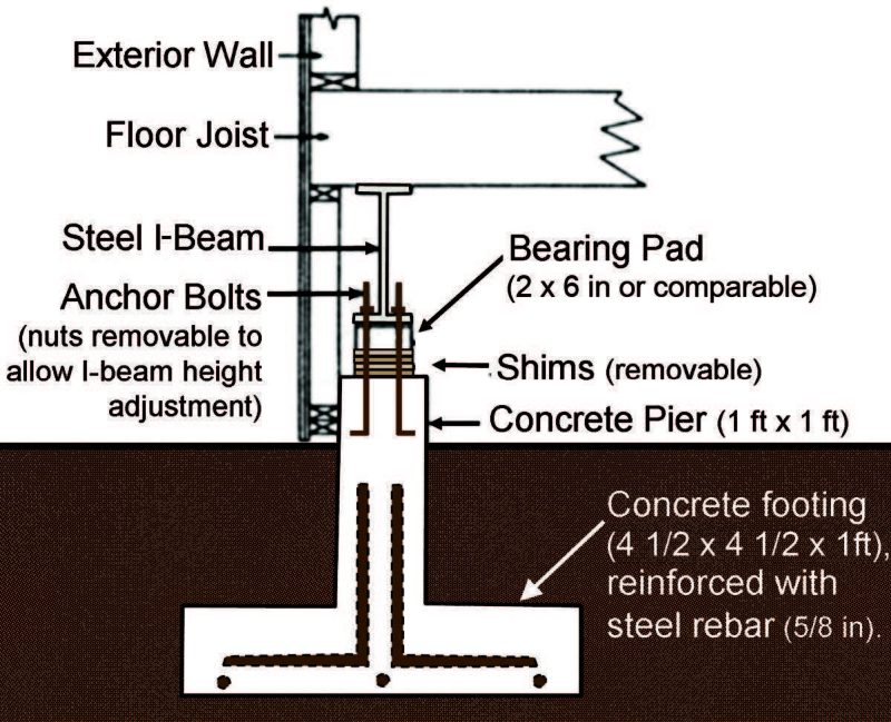
Begley, Gray, and Zickefoose (1986) have presented a detailed design for a flexible, single-story residence using pier foundations and an expansion-joint system (figure 3). Basically, the house rests on two 30-foot by 30-foot stiff-frame platforms supported by piers sym-metrically placed at 15-foot intervals. A flexible-joint system allows for considerable horizontal and vertical movement between sections. The pier-frame connections allow for loosening the anchor bolts and adding or removing shims, as required. Three inches of metal shims of varying thicknesses are built-in for this purpose, and a 6-inch rubber-bearing pad above the shims provides additional flexibility and helps accommodate horizontal movements. Wide-flange steel beams (18 inches) are recommended to provide the stiff frame and bridge between piers. This pier-frame system adds nearly 10 percent to the cost of the structure over more conventional construction, but the design clearly shows that it is practical to design flexible residential structures on adjustable foundations.
Figure 3. Detail of an adjustable foundation for residences in subsidence-prone areas, based on Begley, Gray, and Zickefoose (1986).
With some additional innovation, it is possible that elements of both the GAI adjustable-bolt design and the Begley pier-frame design can be combined to provide an economical, easily adjusted foundation system. A method of adjustment could be to jack the beam above a settled pier back to level, and to wedge shims between the pier cap and beam. If the pier cap-beam connections – which must provide anchorage against both uplift and lateral forces as well as support from below – are designed to allow shimming, the procedure should be relatively inexpensive. In reclaimed mine areas, the structure must also be able to respond to potential horizontal movements of the supporting piers. Such ability might be obtained by using slotted plates at the pier-beam connections. Additional flexibility might be built into the pier cap-beam connection by incorporating rubberized items, such as heavy-machinery engine mounts, into the connector design. Construction economies might be obtained by spanning piers with pres-sure-treated laminated wood beams rather than steel.
An important element of any adjustable foundation structural design will be to incorporate a mechanism to accommodate periodic checks of the structure’s bearing and consequent need for releveling. Conceivably, in areas where delivered concrete costs are high, a well-designed and executed adjustable pier-and-post foundation could be less expensive than a perimeter wall foundation due to the reduced use of concrete.
Conclusions
The land-use problems of the Appalachian coalfields are unique; finding solutions to these problems will be vital to the region’s future. There will be opportunities to locate many homes, as well as commercial and industrial structures, on settlement-prone sites. If the required investments are to provide benefits over the long term, these structures must be designed for the unique conditions of available land in the coal production areas.
Two major types of settlement occur in deep fills. Creep settlement occurs routinely, due to the sheer weight of loose earth materials; the rate of creep settlement decreases with time. Hydroconsolidation is settlement that is induced by water saturation of the fill materials. If the fill becomes saturated, this type of settlement occurs rapidly. Once creep settlement has slowed to an acceptable rate and hydroconsolidation has occurred, filled land may be treated as essentially stable ground.
Recently constructed deep fills, however, will be prone to settlement for many years and are generally unsuited for the types of foundations commonly used to support housing. This study suggests adjustable foundations as one means for adapting housing to settlement-prone sites. Currently, adjustable foundations are not employed to any considerable extent in Appalachian areas. One cannot purchase ready-made, adjustable foundation-pier connectors from local sources. However, adjustable foundation elements could be fabricated from commonly available materials – such as steel plates and heavy threaded rods – using equipment such as the torch, welder, and heavy drill. Ultimately, in years to come, innovative design by local residents and industries could lead to housing systems adapted to the unique conditions of settlement-prone sites in the Appalachian coalfields.
Recommendations
For residential construction on settlement-prone sites in mining regions of central Appalachia, a number of precautions should be taken. These are itemized below as recommendations.
- All recently reclaimed land in surface mined areas should be considered as potentially unstable ground, subject to settlement – even where normal engineer-ing precautions for good stabilization have been taken in the placement of the fill – unless an engineer can certify that site conditions are such that potential settlement is likely to be of little consequence.
- The amount of settlement that can be expected to occur is a function of a number of factors, including depth of fill and degree of compaction upon placement. A major factor that cannot be controlled during fill construction is the subsequent water content of the fill. Changes in the water content of the fill can induce settlement, even when the best engineering practices have been utilized during construction. Thus, owners of homes constructed on mined lands should endeavor to keep excessive water out of the fill that supports the structure.
- Homes constructed on filled lands should be placed so as to minimize potential settlement and distortion.
- Unless it can be established that settlement will definitely be a problem or the homeowner is willing to risk the effects of settlement that occur, homes constructed on filled lands should be designed to accommodate settlement without suffering severe damages.
- When adjustable foundations are used, these should provide anchorage against uplift and accommodate both horizontal and vertical movements of the supporting piers; provision should be made for periodic checks of the structure’s bearing and for adjustment of the structure’s individual support points when necessary. Appropriate engineering, based upon an understanding of the geotechnical properties of deep fills, can lead to the successful utilization of reclaimed mined lands for building construction and development. Anyone considering construction on fill materials or in areas over mineable coal reserves should consult a professional engineer with a geotechnical background.
References
Powell River Project/Virginia Cooperative Extension publications: Available from Powell River Project (www.cses.vt.edu/PRP/) and Virginia Cooperative Extension (www.ext.vt.edu).
Zipper, C. E., R. B. Reneau Jr., and M. Saluta. Updated 2009. On-Site Treatment and Disposal of Residential Wastewaters on Mined Lands. Virginia Cooperative Extension publication 460-142; www.pubs.ext.vt.edu/460/460-142/460-142.html.
Zipper, C. E., and S. Winter. Updated 2009. Stabilizing Reclaimed Mines to Support Buildings and Development. Virginia Cooperative Extension publication 460-130; www.pubs.ext.vt.edu/460/460-130/460-130.html.
Other References
Begley, R. D., L. E. Gray, and G. M. Zickefoose. 1986. Design considerations for structures to be built on subsidence prone land. Second Workshop on Surface Subsidence Due to Underground Mining, Morgantown, W.Va.
GAI Consultants Inc. 1983. Survey of ground conditions affecting structural response to subsidence. Prepared for the U.S. Bureau of Mines. Pittsburgh, Pa.: GAI Consultants.
U.S. Department of the Army. 1983. Foundations in expansive soils. TM5-818-7, Washington, D.C.: Department of the Army. www.army.mil/USAPA/eng/DR_pubs/dr_a/pdf/tm5_818_7.pdf (accessed Jan. 20,2009).
Virginia Cooperative Extension materials are available for public use, reprint, or citation without further permission, provided the use includes credit to the author and to Virginia Cooperative Extension, Virginia Tech, and Virginia State University.
Virginia Cooperative Extension is a partnership of Virginia Tech, Virginia State University, the U.S. Department of Agriculture, and local governments. Its programs and employment are open to all, regardless of age, color, disability, sex (including pregnancy), gender, gender identity, gender expression, national origin, political affiliation, race, religion, sexual orientation, genetic information, military status, or any other basis protected by law
Publication Date
July 26, 2023