

Fine Tuning a Sprayer with “Ounce” Calibration Method
ID
442-453 (BSE-320P)
This extension publication discusses guidelines to quickly evaluate the performance of a sprayer. Sprayer calibration, nozzle discharge, spray pattern uniformity, speed checks, pump performance, and plumbing arrangements are evaluated with minimal calculations.
Tractor-mounted, pull-type, pick-up-mounted and self-propelled sprayers are available from numerous sources. Rising chemical costs and new low-rate products are making accurate application more important than ever before. Proper calibration must be a primary management consideration whether one is a farmer or a custom applicator. Since most pesticides are applied with hydraulic sprayers, users should know proper application methods, chemical effects on equipment, and correct cleaning and storage methods.
Proper sprayer application depends on many factors. These include:
sprayer design;
nozzle type;
boom height;
operating pressure;
agitation (for liquid suspensions); and
ground speed.
Consider these factors, while following label directions, to ensure products are applied correctly. For example, the labels of products intended to be applied by sprayers may specify a droplet size. Droplet size requirements, in turn, affect nozzle selection and operating pressure. Labels often require or recommend a volume of finished spray to apply per unit area. Ensuring that a system is delivering the right amount involves proper nozzle selection and placement. It also influences operating speed and, to a lesser degree, pressure. More and more, product labels specify or set limits on boom height, ground speed, and nozzle type. Product distribution—for example, broadcast or banded application—will dictate sprayer configuration and nozzle selection. Materials that suspend vs. dissolve in a carrier must be applied with equipment having agitation sufficient to keep the product uniformly mixed.
Chemicals will be applied correctly when users follow product label directions, and configure and operate equipment properly. For spray applications, proper application also requires careful and accurate mixing. The goals of any application are to achieve efficacy while minimizing off-target movement. After consulting the label, proper nozzle selection is a key step in ensuring that you are “in the ballpark” when you start the calibration process. Two things to consider when choosing nozzles are label-mandated system output (application rate or nozzle type) and droplet size. Both are very important because they affect coverage and drift (See VCE Publication, Nozzles: Selection and Sizing).
Preseason visual checks are not adequate for accurate application, nor is the fact that the equipment and nozzles are new. In several surveys, only one of three applicators was applying within +/- 5 percent of estimated rate. Thus, checking all nozzles for correct flow rates and uniform application and calibrating the sprayer cannot be eliminated. Manufacturers’ catalogs are guidelines, but fine-tuning of a sprayer is the operator’s responsibility. Sprayers should be calibrated every time a different pesticide is applied, and recalibrated whenever equipment is reconfigured—for example, when changing nozzles or boom height. In addition, a sprayer should be recalibrated at least every other day when in continuous use. Since these checks may have to be performed often, evaluating
Determining Gallons per Acre (gpa)
The purpose of any calibration method is to determine the number of gallons of finished spray mix that will be applied per acre. Subsequently, the gallons applied per acre can be used to determine the quantity of active ingredients to add to the spray tank. Before you start: 1) Check each nozzle / nozzle set on the boom for uniform output. 2) Flush the sprayer and load it (about half-full) with clean water. The following method requires: a stopwatch, a container for collection, a tape measure, marking flags, and a scale or container graduated in ounces. The procedure is as follows:
STEP 1. Select the distance according to the nozzle spacing on the broadcast boom shown in Table 1. When using a directed or banding rig, use the row spacing. Measure the correct distance in a level field. The distance measurement may be marked off in a permanent fashion. The travel area should be typical of the surface and soil conditions of the area to be sprayed. Many tractors and sprayers will gain or lose in excess of 10% of desired travel speed while moving up and down slopes. If field variations are wide, several test areas may be needed. Remember, this traveled distance will give a clue to the actual speed the sprayer is going under field conditions; therefore, the measured distance and timing must be exact.
STEP 2. Drive and time the sprayer in seconds (Figure 1) at the throttle setting and load that normally occurs during spraying (spray tank should be 1/2 to 2/3 full) over the marked area. Engage the incorporation equipment (disk, planter, etc.) or other devices used while spraying. Do not change the gear or throttle setting after you have chosen a spraying speed. A change in ground speed will change the sprayer application rate and this will require recalibration.
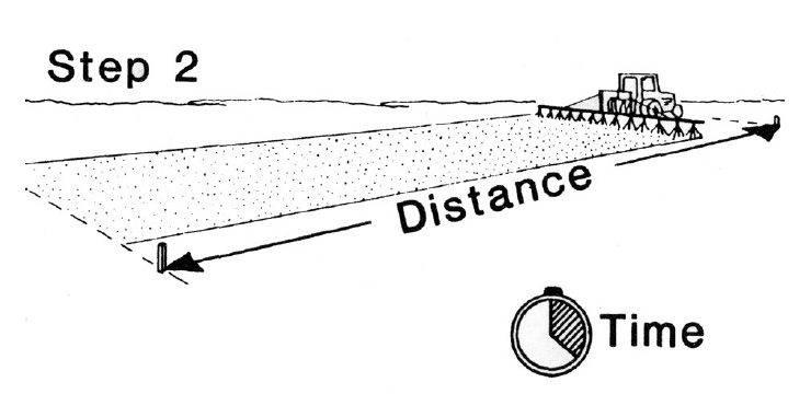
Table 1. Calibration distances and speeds for varying nozzle or row spacing.
| Nozzle or Row Spacing (in) | Calibration Distance (ft) | Time in Seconds for Various Ground Speeds (mph)* | |||||||
|---|---|---|---|---|---|---|---|---|---|
| 3.0 | 3.5 | 4.0 | 4.5 | 5.0 | 6.0 | 7.0 | 8.0 | ||
| 40 | 102 | 23.2 | 19.9 | 17.4 | 15.5 | 14.0 | 12.6 | 9.9 | 8.7 |
| 38 | 107 | 24.3 | 20.8 | 18.2 | 16.2 | 14.6 | 12.2 | 10.4 | 9.1 |
| 36 | 113 | 25.7 | 22.0 | 19.3 | 17.1 | 15.4 | 12.8 | 11.0 | 9.6 |
| 34 | 120 | 27.3 | 23.4 | 20.5 | 18.2 | 16.4 | 13.6 | 11.7 | 10.2 |
| 32 | 127 | 28.9 | 24.7 | 21.6 | 19.2 | 17.3 | 14.4 | 12.4 | 10.8 |
| 30 | 136 | 30.9 | 26.5 | 23.2 | 20.6 | 18.5 | 15.5 | 13.2 | 11.6 |
| 28 | 146 | 33.2 | 28.4 | 24.9 | 22.1 | 19.9 | 16.6 | 14.2 | 12.4 |
| 24 | 170 | 38.6 | 33.1 | 29.0 | 25.8 | 23.2 | 19.3 | 16.6 | 14.5 |
| 22 | 185 | 42.0 | 36.0 | 31.5 | 28.0 | 25.2 | 21.0 | 18.0 | 15.8 |
| 20 | 204 | 46.4 | 39.7 | 34.8 | 30.9 | 27.8 | 23.2 | 19.9 | 17.4 |
| 18 | 227 | 51.6 | 44.2 | 38.7 | 34.4 | 31.0 | 25.8 | 22.1 | 19.3 |
| 16 | 255 | 58.0 | 49.7 | 43.5 | 38.6 | 34.8 | 29.0 | 24.8 | 21.7 |
| 14 | 291 | 66.1 | 56.7 | 49.6 | 44.1 | 39.7 | 33.1 | 28.3 | 24.8 |
* 1 mph = 88 feet per minute
+ Note: for times less than 20 seconds (shaded area) improved accuracy can be attained by doubling the collection time (STEP 3.) and dividing the output collected by two.
STEP 3. While in a stationary position, bring the power unit to the proper throttle setting and sprayer to the correct boom pressure used in Step 2. Catch the nozzle discharge for the time recorded in Step 2, using a container intended to measure fluid ounces. If more than one nozzle per row is used (direct, insecticide or fungicide rigs), catch the discharge of all nozzles within the row spacing selected in STEP 1. Then combine the amount of discharge from all nozzles spraying in that row or band.
Remember, from a safety point of view, use clean water only! Even though you will be collecting water, protective clothing according to label instructions.
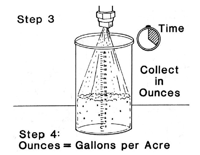
STEP 4. The total discharge measured in ounces is equal to gallons per acre (gpa) applied. Since this calibration was based on water, conversion factors (Table 2) must be used when spraying solutions that are heavier or lighter than water. Multiply the observed rates by the conversion factors to attain accurate rates using the spray solutions.
Example of “Ounce” Calibration Suppose a sprayer was set-up with 30 inch nozzle spacing. Step 1. Using Table 1, 136 feet was marked off and the sprayer was driven through and timed. Step 2. The time recorded was 21 seconds. According to Table 1, the travel speed was about 4.5 mph. Step 3. In a stationary position, the sprayer was brought to the proper pressure. A nozzle was collected for 21 seconds as found in Step 2. The discharge was measured to be 15 fluid ounces. Step 4. The calibration was 15 gallons per acre. Several nozzles should be measured and averaged from different sections on the boom (ie., left, right, and center) for a more reliable measurement.
Suppose the actual carrier will be 28% fertilizer and not water. The carrier rate should be adjusted. Using Table 2, the carrier rate would be: [15 gpa * .885 (Table 2)] = 13.3 gpa. This would be the value used to determine the proper amount of active ingredient to add to the spray tank.
| Density of Solution (lb/gal) | Specific Gravity | Conversion Factors |
|---|---|---|
| 7.0 | .84 | 1.092 |
8.0 |
.96 | 1.021 |
| 8.34 WATER | 1.00 | 1.000 |
| 9.0 | 1.08 | .963 |
| 10.0 | 1.20 | .913 |
| 10.65 28% nitrogen solution | 1.28 | .885 |
11.0 7-27-7 fertilizer |
1.32 | .871 |
| 11.06 32% nitrogen solution | 1.33 | .868 |
| 11.40 10-34-0 fertilizer | 1.37 | .855 |
| 11.50 12-0-26 fertilizer | 1.38 | .852 |
| 11.60 11-37-0 fertilizer | 1.43 | .848 |
| 12.0 | 1.44 | .834 |
| 14.0 | 1.68 | .772 |
Calibrate Frequently... The “ounce” calibration method describes a procedure without calculations that can be used to evaluate the output from a hydraulic sprayer. When changing the application rate and system output: change nozzles for large adjustments, change speed for modest changes (within safety limits), and pressure for minor adjustments. Always recalibrate following such changes.
Most farmers use the “Known Area” calibration method. This method requires the operator to mark and spray a known area, determine the number of gallons of liquid applied to that area, compare the amount applied to what the label calls for, and adjust as needed. Gallons per acre can be calculated by dividing the number of gallons applied by the known acres method is useful, but it takes considerable time and effort, and must be done in advance. It is NOT useful for “work in progress” because a misapplication may occur before being detected.
Band Application Calibration
The same calibration methods can be used to calibrate band application. The only difference is the amount of area covered. Total acres refers to the entire area of the field. This would include the sprayed band and the area between the bands. A treated acre refers only to the treated area in the bands. The spray that would be discharged by the broadcast rate is concentrated in a narrow band by the ratio of row spacing to band width (Table 3). In band spraying, the row spacing and the nozzle spacing are the same. After performing the Steps 1-4 of the above procedure, multiply the answer by the appropriate conversion factor to attain band rate.
Table 3. Conversion factor to convert broadcast rate (gallons per total acre) to band rate (gallons per treated acre).
| Band width (in) | Row spacing (in) | |||
|---|---|---|---|---|
| 20 | 30 | 36 | 40 | |
| 8 | 2.5 | 3.8 | 4.5 | 5.0 |
| 10 | 2.0 | 3.0 | 3.6 | 4.0 |
| 11 | 1.8 | 2.7 | 3.3 | 3.6 |
| 12 | 1.6 | 2.5 | 3.0 | 3.3 |
| 13 | 1.5 | 2.3 | 2.8 | 3.1 |
| 14 | 1.4 | 2.1 | 2.6 | 2.9 |
| 15 | 1.3 | 2.0 | 2.4 | 2.7 |
| 16 | 1.2 | 1.9 | 2.3 | 2.5 |
Unless otherwise specified, chemical application rates are given on a broadcast basis. For band applications, the rate per treated area is the same as the broadcast rate, but the total amount of pesticide used on a field is less because only a portion of the field is treated.
Nozzle Discharge and Uniformity Check
Nozzle condition is very important for uniform application. Observe the spray pattern from each nozzle. If the spray pattern is not uniform from visual observations, large output variations exist. Often poor spray patterns are due to clogged nozzles and strainer components. Remove debris from a nozzle, screen, or filter by using a specially-designed brush with nylon bristles. Nozzle-cleaning kits, using a stream of air (~ 50 psi), are available. Flat-fan nozzle may be unplugged with a wooden or plastic pick; however, a pick will not unplug low-drift nozzles with pre-orifice and/ or air-induction chambers. Never use a metal object when cleaning a nozzle or strainer. DO NOT use your mouth to clean (blow through) the nozzle orifice.
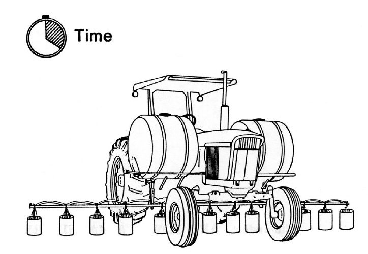
Check nozzle discharge uniformity (Figure 3) by repeating STEPS 3 and 4 above for all nozzles. OR use a flow meter to check all nozzle/nozzle sets and compare flow rate with the one(s) used in the calibration test. If a worn or damaged nozzle is identified, replace it. If a clogged nozzle can not be cleared, it too must be replaced. To make an effective broadcast application, all nozzles on a boom must match (pattern, flow rate, and type). If large variation is found within the nozzle set, it may be best to purchase new ones. Calculate the average flow rate for all the nozzles on the boom. If most of the individual nozzles vary more than +/- 5% from the average, replace all the nozzles. After adjustment or correction, recalibrate. To calculate the gallons per minute (gpm) discharge of a nozzle, use: gpm = ounces collected x 0.47 / time (in seconds).
The flow rate (gpm) can be adjusted slightly by changing pressure. However, to double the output, the pressure must be increased four times. High pressures (>45 psi) may exert excessive strain on sprayer components, increase wear on the nozzles, and produce drift-susceptible fine droplets. Low pressures will not develop a full width spray pattern for each nozzle. This, in turn, may result in poor coverage and untreated streaks. If more discharge is required, the best methods are to use nozzles with larger orifices or reduce travel speed. Remember the limits because most nozzles perform best at (or near) the mid-point of their pressure range ratings.
The relationship between gallons per acre (gpa) and nozzle output in gallons per minute (gpm) can be determined by using the sprayer speed in miles per hour (mph) and spray width in inches (w) using the following equation:
gpa = 5940 x gpm / mph x w
where: w = nozzle spacing in broadcast or band spraying, spray swath of boomless spraying or row width of directed rigs.
Do not use nozzles of different materials, types, discharge angles, or gallon capacity on the same sprayer. Mismatched nozzles will produce uneven spray patterns. Select the correct type of nozzle orifice size and spray pattern for the intended job. Know the specific use of a nozzle tip (see VCE Publication: Nozzles: Selection and Sizing).
Another factor influencing spray uniformity is boom height. Boom height controls the amount of nozzle pattern overlap. As a rule, best performance of a broadcast sprayer is when the nozzle spacing, height, and angle provide for 100% overlap at the target height. Consult nozzle manufacturer catalogs for recommendations regarding boom height and nozzle spacing. Note that some product labels may have specific requirements regarding sprayer configuration. Booms should be relatively rigid in all directions. Swinging back and forth or up and down is undesirable. Gauge wheels mounted near the boom ends should help to maintain a uniform boom height.
One way to check uniformity at the ground surface or target height of broadcast and banded rigs is to use a corrugated pattern check tray. Due to cost, these devices may not be practical for all applicators. However, a quick check of uniformity can be performed by spraying over a hot slab of concrete. Then watch the drying patterns. Uneven drying may indicate worn, damaged, plugged, or mismatched nozzles.
Ground Speed Check
A survey of field sprayers indicated 65 percent of the operators had errors of greater than 5 percent in estimated travel speed. STEP 2 of the described sprayer evaluation method provides a clue to the actual speed the sprayer was traveling under field conditions. Accurate application requires that the operator know exactly how fast the sprayer moves over the ground surface. Because of wheel slippage and rough surface conditions, the actual rig velocity is often different from the tachometer and speedometer readings. For a more accurate measurement of travel speed mark off a distance of 220 feet. Drive and time the operation as in STEP 2. The speed is calculated as:![]()
mph = 150 / seconds timed
Application rate can be effective changed by changing operating speed. For example, the faster traveled, the less applied per area. The slower traveled, the more applied. By doubling the speed, the application rate will be reduced by one-half. By reducing the speed by one-half, the application rate will double. Large changes in application rate can be changed with speed. However, practical limits exist. They include operator safety; wear-and-tear on equipment; an unstable boom, which may result in uneven, poor coverage; and high boom placement, which increases the risk of spray particle drift.
Pump Pressure Check
The pump output should have at least 20 percent more capacity than the largest volume required by the nozzles. A pump with reserve capacity will allow for proper agitation and deliver the necessary volume as the pump wears (see VCE Publication - Plumbing Systems of Agricultural Sprayers).
The pump should be evaluated if the system is not receiving adequate pressure. In order to check pump capacity, disconnect the outlet side of the pump and put the hose in a 55 gallon drum. Run the pump at the throttle setting normally used during spraying. Measure the time (in minutes) required to fill the drum. Calculate the pump capacity by dividing 55 gallons by the minutes measured. If the pump’s capacity is too
Strainers and Screens Check
The sprayer should be equipped with several strainers and screens. The more strainers and screens used, the less chance a nozzle will become plugged. A 10 to 20 mesh basket strainer should be used in the tank manhole. This strainer will stop large items such as label booklets. Sometimes these booklets are loosely attached to the container and can fall into the tank while adding chemicals.
A 50 mesh strainer should be placed on the outlet side of the pump and should be cleaned frequently. Using a large screen on the inlet side of the pump will keep sand, gravel, or debris from damaging the pump. Additional strainers should be placed after the flow control assembly. Cleaning a strainer is easier than cleaning each nozzle screen. Each nozzle should have a 50 to 100 mesh screen to stop any particles that may plug the nozzle. Check the manufacturer’s recommendations for the exact screen size. Remember, partly plugged orifices and screens are hard to detect, so clean them regularly.
Spray Monitor and Controller Check
Spray monitors and controllers are becoming more popular to achieve uniform application, but they do not eliminate the good practices of sprayer inspection and calibration. System monitors record the operating conditions such as travel speed, pressure, and/or flow rate. Spray controllers are monitors with the added capability of automatic rate control. The controller goes a step further than a monitor and receives the actual application rate from the monitors and compares it to the desired rate. If a difference exists, the controller will adjust the application rate automatically (usually by adjusting pressure). Since these adjustments are a direct response to various sensors, it is important that these sensors are periodically calibrated. Remember rate controllers compensate for plugged, worn, damaged, or mismatched nozzles. An operator will see the preset or expected GPA, but the application may not be uniform. Do not assume that the electronic systems are foolproof. Consult the manufacturer’s operators manual to properly calibrate and adjust the sensors.
Conclusions
Spray equipment in good condition will apply chemicals properly if frequently calibrated and correctly operated. Manufacturer’s manuals include tables to show rates of application for various nozzles, pressures, and ground speeds. Use this information to initially set up the sprayer, then use the methods described in the publication to evaluate and adjust the sprayer for accurate application.
Acknowledgments
The authors acknowledge the contributions made by Kevin Bradley, Scott Hagood, and Henry Wilson in previous versions of the factsheet.
Resources
Droplet Chart / Selection Guide, Virginia Cooperative Extension publication 442-031 (BSE-263P); https://www.pubs.ext.vt.edu/442/442-031/442-031.html (accessed: February 2020)
Nozzles: Selection and Sizing, Virginia Cooperative Extension publication 442-032 (BSE-262P); https://www.pubs.ext.vt.edu/442/442-032/442-032.html (accessed: February 2020)
Plumbing Systems of Agricultural Sprayers, Virginia Cooperative Extension publication 442-452; https://www.pubs.ext.vt.edu/442/442-452/442-452.html (accessed: February 2020)
Strategies to Reduce Spray Drift, Kansas State University Agricultural Experiment Station and Cooperative Extension Service publication MF-2444;
https://bookstore.ksre.ksu.edu/pubs/MF2444.pdf (accessed: February 2020)
Weight and Measures Conversions
Weight
16 ounces = 1 pound = 453.6 grams
1 gallon water = 8.34 pounds = 3.78 liters
Liquid Measure
1 fluid ounce = 2 tablespoons = 29.57 milliliters
16 fluid ounces = 1 pint = 2 cups
8 pints = 4 quarts = 1 gallon
Length
3 feet = 1 yard = 91.44 centimeters
16.5 feet = 1 rod
5280 feet = 1 mile = 1.61 kilometers
320 rods = 1 mile
Area
9 square feet = 1 square yard
43560 square feet = 1 acre = 160 square rods 1 acre = .405 hectare
640 acres = 1 square mile
Speed
88 feet per minute = 1 mph 1 mph = 1.61 km/h
Volume
27 cubic feet = 1 cubic yard
1 cubic foot = 1728 cubic inches = 7.48 gallons 1 gallon = 231 cubic inches
1 cubic foot = 0.028 cubic meters
Common Abbreviations and Terms Used:
gpm = gallons per minute gpa = gallons per acre
psi = pounds per square inch mph = miles per hour
rpm = revolutions per minute gph = gallons per hour
fpm = feet per minute
Virginia Cooperative Extension materials are available for public use, reprint, or citation without further permission, provided the use includes credit to the author and to Virginia Cooperative Extension, Virginia Tech, and Virginia State University.
Virginia Cooperative Extension is a partnership of Virginia Tech, Virginia State University, the U.S. Department of Agriculture, and local governments. Its programs and employment are open to all, regardless of age, color, disability, sex (including pregnancy), gender, gender identity, gender expression, genetic information, ethnicity or national origin, political affiliation, race, religion, sexual orientation, or military status, or any other basis protected by law.
Publication Date
April 16, 2020
