

Electric Fencing: How to Install a Grounding System
ID
SPES-691P
 EXPERT REVIEWED
Introduction
An adequate grounding system is essential for an effective electric fence. Unfortunately, poor grounding is a leading cause of problems with electric fencing. This publication, one of a series on Electric Fencing, reviews how to size and install a grounding system to maximize the shocking potential of the electric fence.
Installing a grounding system
- Establish the proper location. The location of the grounding system should be at least 33 feet away from utility grounds, your service box ground, and metal water pipes. Do not touch metal buildings and use insulated lead-out wire to get past buildings. Locate the grounding system in a location that has the best chance of remaining moist in a summer drought (e.g., under a roof eave).
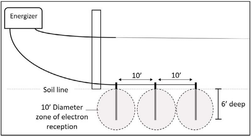
- Determine the number and type of ground rods needed. Industry guidelines recommend installing a minimum of three ground rods driven six feet deep into moist soil for energizers up to 15 joules, five rods for energizers up to 25 joules, and seven rods for energizers up to 35 joules. These are general guidelines that should be adapted to your scenario; soils with poor conductivity could require more than the recommended minimum. For most small solar energizers, a single 3-foot portable ground rod with a T-handle for easy removal works well. For a ground rod to be effective, it should have at least 6 feet in moist soil. Therefore, in a scenario where three ground rods are recommended, there must be 18 total feet of ground rod length in moist soil (3 rods x 6 feet = 18 feet). If you can’t get ground rods to go 6 feet deep, use additional rods to achieve the total required feet of ground rods contacting moist soil.
- Map out placement for ground rods. Place ground rods at least 10 feet apart to minimize electrical resistance and maximize the reception field and electron flow from the soil into the grounding system (fig. 1).
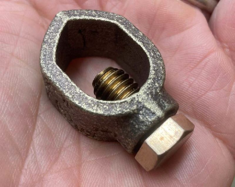
Select which type of ground rods, ground rod connecting wire, and rod clamps to use. If possible, use one unbroken wire to connect all ground rods, and use ground rod clamps to make a tight connection to each rod. For energizers less than 20 joules, the use of 12 ½ gauge galvanized steel fence wire is adequate to connect ground rods. Energizers greater than 20 joules require the use of high-conductive lead-out cable or 6-gauge copper wire. While mixing metals (i.e., copper and steel) is not recommended due to the potential of corrosion, copper wire can be paired with steel ground rods if stainless steel or bronze ground rod clamps are used (fig. 2).
Use only galvanized steel ground rods with galvanized wire and stainless steel or bronze clamps. Copper ground rods may be used if a copper ground wire is used, but mixing copper and galvanized steel will result in corrosion and poor electrical conductivity. Rebar or other repurposed items should not be used for ground rods because rust and corrosion typically reduce their conductivity.
Soil treatment
When grounding in very dry or sandy soils, or when using a very high-output energizer, it may be necessary to regularly water the soil at the ground rod. A super- grounding mixture can also be used to immediately improve conductivity of the soil close to the grounding system. To administer the mixture, dig a hole around the top of each ground rod and pour in a slurry mixture of water with two parts bentonite to one part coarse rock salt.
If rods cannot be driven into the ground, they may be laid in open trenches with the super-grounding slurry applied. This mixture is extremely corrosive, so stainless steel rather than galvanized ground rods should be used. In addition, ground rod placement should be extended at least 35 feet apart. During dry weather, water will need to be added to the holes.
The super-grounding mixture is not a permanent fix but should remain effective for several years.
Issues with lightning damage to energizers
If you have repeated issues with lightning damage to energizers after installing a good surge protector and lightning diverter, it could be that your electric fence grounding system is a better ground than that of the residential electric service. When lightning hits a nearby power line, the electrical surge can bypass the residential service ground and travel through the energizer to get to your fence’s grounding system. To remedy this, ask an electrician about installing additional ground rods to your residential grounding system.
Acknowledgements
Thank you to the technical reviewers for this publication: Steve Jones, Conservation Specialist, John Marshall Soil and Water Conservation District; Sydney Beery Electric Fence Energizer Repair; Phil Blevins, Extension Agent, Washington County; and Scott Jessee, Extension Agent, Russell County.
Virginia Cooperative Extension materials are available for public use, reprint, or citation without further permission, provided the use includes credit to the author and to Virginia Cooperative Extension, Virginia Tech, and Virginia State University.
Virginia Cooperative Extension is a partnership of Virginia Tech, Virginia State University, the U.S. Department of Agriculture (USDA), and local governments, and is an equal opportunity employer. For the full non-discrimination statement, please visit ext.vt.edu/accessibility.
Publication Date
May 12, 2025
