On-Site Sewage Treatment Alternatives
ID
448-407 (SPES-520P)
 EXPERT REVIEWED
Preface
The types of decentralized (onsite) systems (conventional or alternative) are described by the EPA (https://www.epa.gov/septic/types-septic-systems).
The purpose of this publication is to describe on-site technologies for treating domestic sewage where conventional systems (septic tank with drainfield) are not an option (U.S. EPA 2002). These technologies are described as alternative systems in this publication.
Our goal is to provide information that can be used by property owners and residents to initiate action to rectify sewage disposal problems, especially where current wastewater treatment is inadequate. This document is intended to provide information on alternative wastewater treatment options that will help the reader make informed decisions when dealing with oversight agencies and contractors; it is not intended to serve as a stand-alone reference for design or construction.
Introduction
According to the 2010 U.S. Census, about 19.4 percent of U.S. households surveyed used on-site systems for sewage disposal (U.S. Census Bureau 2013; see table C-04-AO on page 14). By 2017, that number had dropped slightly to 17.9 percent (https:// bit.ly/45qGvp5). In Virginia, about 30 percent of the houses have septic or cesspool systems, a rate that is about one-third higher than the national average (https://bit.ly/3FdY29k). New single-family homes in the US started in 2021 are served by individual wells and 16% have private septic systems, and is 19% in the region that includes Virginia (https://bit. ly/46pPZlM). Most sewage disposal systems are conventional septic systems (septic tank and drainfield in nearby soil), although alternative systems are increasing in use in areas with less-suitable soils. About 35% of Virginia’s systems are the alternative type (https://bit.ly/3FdY29k).
Inadequate sewage disposal due to failing or nonexistent on-site treatment is a problem in many Virginia communities. U.S. Environmental Protection Agency (U.S. EPA 2003) fact sheets estimate that 10 to 20 percent of on-site wastewater systems malfunction each year. In Virginia, more than 28 percent of the houses have septic or cesspool systems, a rate that is higher than the national average of 20 to 25 percent.
Why Is Sewage Treatment Important?
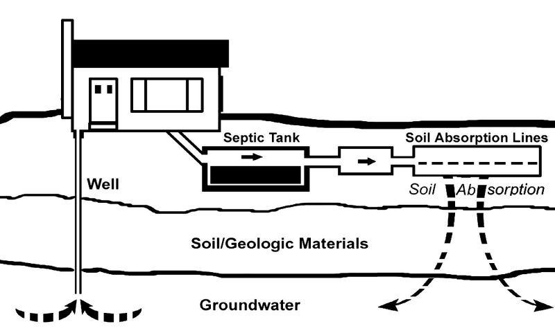
Effective sewage treatment prevents a variety of ailments that can be spread by exposure to pathogens present in untreated sewages (Reneau, Hagedorn, and Degen 1989). Discharges of untreated sewage can contaminate groundwaters and surface waters used for drinking, recreation, and fish and shellfish fisheries (fig. 1).
Inadequate sewage disposal due to failing or nonexistent on-site treatment is a problem in many Virginia communities. U.S. Environmental Protection Agency (U.S. EPA 2003) estimates that at least 10 percent of onsite systems back up onto the ground surface or into the home each year. Other data have shown that at least 20 percent of systems are malfunctioning to some degree.
Untreated sewage from failed conventional septic systems or sewage discharged directly into the environment can percolate into groundwater, contaminating drinking-water wells with pathogens. The discharge of untreated sewage to streams can spread disease through direct contact, making such streams unfit for forms of recreation that involve skin contact with the water, such as swimming and boating. Disease can also spread through indirect (secondary) contact with rodents or insects that have received primary exposure and, in turn, harbor the pathogens. Discharged, untreated sewage also can damage ability of the receiving streams to support healthy, living communities of aquatic organisms and can contaminate fisheries.
General Principles of Domestic Sewage Treatment
Raw sewage and septic wastewaters contain a variety of contaminants (table 1). However, many technologies are available to render the sewage suitable for safe discharge to the environment.
Component |
Description |
Mode of Treatment |
|---|---|---|
Solids |
Primarily carbon-based, slowly |
Most are removed by primary treatment (settled by gravity and/or separated by screening or outlet filter).a |
(includes particulates) |
biodegradable organic compounds |
Particulate BOD is removed by primary treatment. |
Biochemical oxygen demand (BOD) |
Biodegradable organic carbon compounds in particulate and soluble forms |
Soluble BOD is consumed by native bacteria in the soil absorption fieldb and/or secondary treatment process that transform carbon-chain organic compounds to carbon dioxide via metabolic processes. Advanced treatment (if present) removes additional BOD. |
Bacterial, viral, and protozoan pathogens |
Disease-causing agents, contaminants of fecal matter |
These organisms, well adapted to the oxygen-poor environment of the human gut, are not well adapted to well-aerated environments. When pathogensare present, some perish in secondary treatment, but some remain in secondary effluent. Pathogens perish in the soil absorption fieldb and/or disinfection processes. |
Nitrogen (N) |
N as organic and ammonium (NH4+) forms | N associated with solids is removed via primary treatment.Some N is volatilized and lost to the atmosphere. Secondary treatment converts much of the remaining N to the nitrate (NO3–) form. Advanced treatment can be installed to remove additional N prior to discharge. |
| Phosphorous (P) | P as organic and inorganic phosphate chemical forms | P associated with solids is removed via primary treatment and in secondary clarifier, if present. P binds to soil particles and is not highly mobile in most soil environments. Advanced treatment can be installed to remove additional P prior to discharge. |
| Household chemicals | Cleansers, detergents, etc. | Minimal treatment. Disposal with septic wastewater should be minimized. |
a Primary treatment tanks (septic tanks) must be cleaned out periodically to maintain system function.
b Absorption field soils must be well-aerated to function effectively.
Most sewage treatment technologies operate by combining basic physical, chemical, and biological processes. Primary, secondary, and advanced treatment technologies are followed by disinfection (fig. 2), whether in conventional or alternative on-sitewastewater systems. Technologies include those used in the municipal treatment works that receive sewage discharged to public sewers in the nation’s developed areas, conventional on-site sewage treatment that uses a septic tank and soil absorption field commonly used in rural areas, and the alternative on-site technologies that form the focus of this publication.
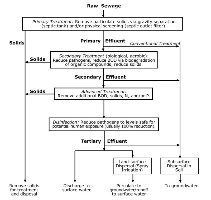
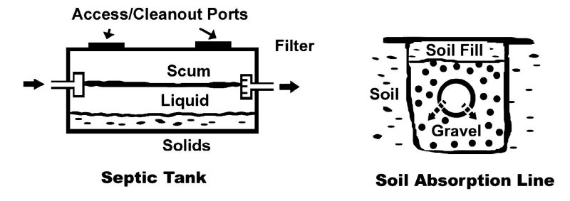
1. Primary treatment removes solids and particles from raw sewage through gravity separation and/or screening. A septic tank is the most common primary treatment device in on-site systems. In alternative systems, the septic tank is commonly outfitted with an outlet filter to capture solid particles that are too small or too light to settle. When added to conventional septic systems, an outlet filter will extend system longevity and improve performance.
Some removal of organic contaminants occurs in the septic tank. Its oxygen-poor environment promotes some decomposition by anaerobic microorganisms, but this process has only a minor effect. The partially treated liquid discharged from primary treatment is called “primary effluent.”
2. Secondary treatment processes, also called “microbial digestion,” receive primary effluent. Most secondary treatment processes move the effluent through an aeration process environment that is favorable to aerobic microorganisms — those that thrive in atmospheric oxygen (O2) environments. The following wastewater renovation processes occur during this treatment.
- Pathogenic microorganism populations are reduced. The vast majority of microorganisms found in sewage thrive within the human digestive system, an anaerobic environment where oxygen does not occur as O2. Consequently, these organisms are not well- adapted to aerated (aerobic) environments. Within secondary treatment devices, some microorganisms (including most pathogens) perish as a result of exposure to O2.
- Other organisms, including predators that consume pathogens, thrive in an aerobic environment, sustained by the rich mix of oxygen with water, biodegradable organic compounds, and essential nutrients that constitute sewage. Where the effluent passes through secondary treatment media with small pores (such as a sand filter or natural soils), pathogen numbers are also reduced via physical straining.
- Biodegradable organic contaminants, such as dissolved organic substances and organic particles, that remain in the primary effluent are removed through microbial activity. The microorganisms in the aerated secondary treatment medium consume and metabolize biodegradable organic compounds, deriving energy by breaking the carbon-carbon bonds and converting the organic carbon into carbon dioxide.
- Small particulate contaminants are removed. Where the filtration media are composed of mineral particles with small pores (such as a sand filter or natural soils), particulate contaminants are removed via physical screening. Biodegradable components of the particles captured in the fine pores are consumed by the resident aerobic bacteria. Partially treated liquid discharged from secondary treatment is called “secondary effluent.”
3. Advanced treatments are optional processes that may be applied to remove additional contaminants from secondary effluent prior to dispersal. Advanced treatment is usually included only in systems intended to discharge directly to the land surface or to surface water streams. Advanced treatment processes designed to remove additional nitrogen and phosphorous from the effluent are sometimes necessary to protect water quality in streams receiving treated effluent discharges.
4. Disinfection systems often rely on chlorination, ozonation, or ultraviolet light. Systems that discharge treated effluent where there is a potential for direct human exposure (i.e., discharged to surface waters or the soil surface) are often required to disinfect the effluent so as to eliminate potential hazards due to human exposure. Effluent that has received advanced treatment and has been disinfected is called “tertiary effluent.”
Treated effluent must be discharged to (or dispersed in) the environment. Secondary effluent is commonly dispersed in soils below the surface, while tertiary effluent may be discharged to flowing waters (such as a surface water stream) or on the soil surface. Surface discharge or dispersal typically requires a permit from an agency responsible for protecting surface water quality as well as an on-site septic system permit.
Conventional On-Site Treatment of Domestic Sewage
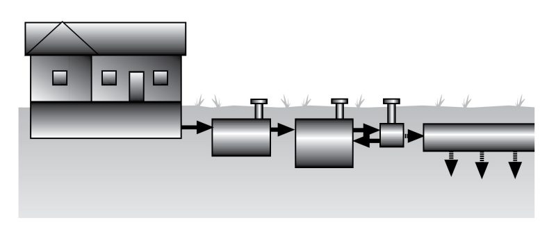
The conventional means of treating sewage with on-site systems is with a septic tank, distribution box, and soil absorption field (fig. 3).
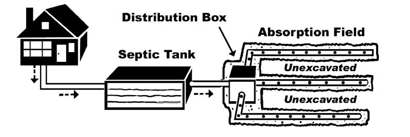
Primary treatment (the removal of solids from the sewage) occurs in the septic tank. If the septic tank fails to perform, solids will enter the distribution box and soil absorption field in large quantities. The accumulated solids will render the septic tank and soil absorption field ineffective. When a soil absorption field or a distribution box begins to clog (plug) with solids, a typical result is an unequal distribution of the effluent. This overloads the absorption lines and areas that are not clogged, which then tend to clog at an accelerated rate. Untreated or partially treated effluent may emerge on the surface in such situations, considered a system failure. A septic tank outlet filter — essentially a screen that captures small particles — can help to ensure against this result.
Regular maintenance and cleaning of the outlet filter is recommended.
The distribution box allocates the effluent equally among several soil absorption lines. It is usually situated below the septic tank outlet so that effluent can move to the distribution box via gravity flow. Because flow through the distribution box also occurs via gravity, the box is leveled during installation to achieve equal distribution of effluent among the soil absorption lines.
Secondary treatment takes place in the soils in the soil absorption field (also called a “drainfield”), where an aerobic environment occurs. The soil absorption lines distribute the effluent to the soil where biological treatment can occur. Effluent moves through soil pores and encounters resident microorganisms. Each absorption line is laid out with a low slope gradient (generally 1/8 to 1/4 vertical-inch per horizontal- foot). The low “pitch” helps distribute effluent evenly along each absorption line’s entire length. Most soil absorption lines are perforated 4-inch PVC pipe laid in gravel-lined trenches.
Effluent emerges from each pipe and percolates through the gravel to the bottom of the trench. Although less common, other absorption-line configurations, including soil infiltration chambers (discussed in the Absorption Lines section in this document), may be used. Advanced treatment and disinfection occur in the soils below and surrounding the absorption trench. A mat of microorganisms called a “biomat” often forms at the trench bottom. The biomat further slows infiltration and allows for further microbial decomposition of organic materials and uptake of excess nutrients from the effluent. State regulations require consideration of soil type and other environmental conditions when an on-site system is designed, and they include the amount of trench bottom required for each 100 gallons per day of the wastewater system’s designed capacity (VDH 2014).
Although the distribution boxes and soil absorption lines are intended to distribute effluent evenly throughout the soil absorption field, it rarely occurs in practice because of the lack of precision in building field systems that depend on gravity for effluent distribution. Therefore, soil absorption fields are commonly larger than would be necessary if precise and even effluent distribution could be assured.
The most common cause of conventional septic system failure is inadequate cleaning of the septic tank and filter, which leads to movement of solids into the absorption lines where they accumulate and impair drainfield function — a condition known as clogging. A qualified septic system contractor should be employed periodically by the homeowner to remove solids from the septic tank, which will minimize this problem.
Other causes of conventional on-site septic system failure can include
- Improper installation, leading to excessive effluent accumulation in one area of the soil absorption field or unintended discharge at the surface.
- Installation of a system that is too small to handle the household’s wastewater production.
- Installation in soils with inadequate capacity or a rate of hydraulic conductivity that is inadequate or excessive.
- Home usage patterns that produce wastewaters in excess of the absorption system’s treatment capacity.
The Virginia Department of Health’s permitting procedures are intended to protect against such problems (VDH 2014). Several guides for homeowners with information on the operation and maintenance of conventional septic systems are available from Virginia Cooperative Extension, “Septic System Best Management Practices” (Brown and Thomas 2022), and “What Happens If My Septic System Fails” (Brown and Thomas 2022), as well as the EPA (https://bit.ly/3Qa3DUq), Maryland Cooperative Extension (https://bit.ly/3toV1jP), and North Carolina Cooperative Extension, including “Septic Systems and Their Maintenance” (Hoover and Konsler 2004), and “Septic System Owner’s Guide” (Hoover 2004). Proper operation and maintenance of conventional and alternative systems is required by law in Virginia.
Alternative On-Site Treatment
There are a variety of alternatives to conventional septic systems available for environmentally sound treatment of sewage produced by the home.
Alternative on-site systems can provide adequate treatment where public sewers are not available and where siting a conventional septic system would not be desirable due to inadequate available soils, a steep slope, or other reasons.
Generally, alternative systems will be more expensive than conventional septic systems. The successful operation of alternative systems normally requires that the systems be checked and serviced on a regular
basis, and many owners ensure proper maintenance by contracting with a qualified business whose employees have been trained to work with these systems.
Most alternative systems combine the basic elements of conventional septic systems with more specialized components. Table 2 lists important on-site sewage technologies and processes reviewed in this publication.
Primary |
Secondary |
Pathogen Removalb |
Effluent Dispersal |
|---|---|---|---|
Septic Tank |
Fixed-media filter |
Chlorination |
Subsurface discharge |
Outlet Filter |
Sand Peat Wetland Mound Suspended-growth Aerobic treatment |
Ozonation Ultraviolet |
Absorption lines Soil infiltration chambers Low-pressure distribution Trickle (drip) irrigation Filtration beds Contour systems Surface discharge Spray irrigation Surface-water discharge |
a Advanced treatment processes are not reviewed in this publication.
b Disinfection (pathogen removal) is not generally required when effluent is dispersed using subsurface soil absorption. When effluent is dispersed at the surface, these processes are typically applied in addition to pathogen removal by primary, secondary, and/or advanced treatment.
A device common to almost all alternative systems is the pump chamber (also called a “dosing chamber”) — a watertight container that holds effluent and houses an electric pump. An electronic controller operates the pump and directs it to operate according to a user- defined schedule.
The pump chamber is usually placed below ground with a covered access opening that protrudes above the surface and is protected from surface runoff inflows. The pump may be directed to operate at multiple-minute cycles at multiple-hour intervals, or it may be directed to turn on for a specified period at specific times each day. By knowing the pump’s per-hour capacity to move effluent applications to a treatment or dispersal device, the amount of effluent applied per dosing cycle can be controlled. Applying effluent in controlled amounts and allowing the receiving system to rest between applications generally aids the processes that are essential to wastewater renovation and environmental dispersal.
The pump-chamber’s storage capacity is an important design parameter because the container should be sized to hold enough effluent to allow effective operation during peak usage periods. If peak usage is concentrated within a few hours of each day, for example, the pump chamber would be designed with sufficient storage to allow the peak period effluent to be held and applied over a longer time period with an adequate margin of safety.
All pump chambers should be outfitted with controls to allow safe usage. A float system, for example, would prevent the pump from cycling on (or turn the pump off) if the wastewater volume held in the chamber falls below a critical level. On the full capacity side, the pump chamber should be outfitted with a float and an overflow alarm so the system operator will be aware of when the system’s capacity is exceeded or the system malfunctions.
Primary treatment takes place in a settling tank. Most often, a conventional septic tank is used as a settling tank, and it is the most cost-effective primary treatment device. Outlet filters used with the settling tank can ensure against the movement of small, solid particles into the secondary treatment or effluent dispersal system. The settling tank’s function and purpose in alternative systems is identical to its role in conventional on-site systems: to remove solid and particulate pollutants from the primary effluent.
Unlike conventional systems, alternative systems provide further treatment of primary effluent. Secondary treatment takes place in fixed-media systems and suspended-growth systems. The secondary treatment unit is critical to successful renovation of primary effluent. Over the years, numerous secondary treatment methods have been developed.
Fixed-Media Filter Systems
Fixed-media systems distribute the primary effluent over a material (or media) that contains solid surfaces that can be populated by aerobic bacteria and other microorganisms. Void spaces within the media allow the movement of both effluent and atmospheric air, exposing the effluent, media surfaces, and resident microorganisms to atmospheric oxygen.
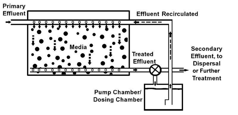
A media-filter system is essentially a watertight chamber containing a permeable media such as sand or peat that supports aerated secondary treatment (fig. 4). Mechanical systems distribute the effluent across the top of the media, collect the treated effluent that has trickled through the filtration media, and recirculate the effluent if desired.
The degree of pretreatment required to achieve safe environmental dispersal combined with the size of the filtration system will determine whether an intermittent (single-pass) or a recirculating media filter is required. An intermittent filter treats each volume of effluent one time, while a recirculating filter subjects each effluent volume to several treatment cycles. Generally, a larger media filtration unit will increase the quality of effluent produced by single-pass treatment, as will recirculation. Recirculating filters can be smaller than intermittent filtration units. However, a single-pass system may contain fewer pumps and less piping and therefore may be easier to maintain and operate.
Raw sewage intended for media-filter treatment receives primary treatment, usually in a septic tank with an outlet filter. The primary effluent is conveyed (typically by gravity) into a holding chamber from which it is pumped to the top of the filtration media and is distributed or sprayed across the media.
Distribution may be by a single spray nozzle in the center of the chamber, by several smaller spray nozzles distributed over the top of the chamber, or by a network of perforated plastic pipes extending across the top of the media. In most cases, the pumping system is designed to deliver effluent with a timed dosing schedule.
Once the effluent has been distributed across the top of the media, gravity causes the effluent to percolate down through the media where resident aerobic organisms render secondary treatment. A method for draining the effluent out of the media must also be provided, usually perforated plastic pipes embedded in the base of the filter unit.
In a once-through treatment system, the secondary effluent drained from the bottom of the filter unit is directed to effluent dispersal or further treatment (advanced treatment and/or disinfection), either by gravity or by pumping, depending on the situation.
With a recirculating system, effluent from the bottom of the media tank is directed to a combination holding tank and pump chamber called a dosing or recirculation tank. The recirculation pumping system is usually set up on a timer so that a certain volume of water from the dosing tank is periodically pumped back to the top of the media. As new effluent enters the system, compensating volumes of treated effluent are discharged (usually from the bottom of the media filter unit) to further treatment or directly to the subsurface soil dispersal system.
Further information on media filters is available through the National Small Flows Clearinghouse (Solomon et al. 1998).
Sand-Based Treatment Systems
When using a mineral material such as sand as a filter, the distribution of size grades is important and must conform to state regulations (VDH 2011). Using a material such as ungraded sand that has many small pores can lead to clogging, while materials with very large pores may not render adequate treatment.
Unfortunately, the cost of obtaining graded mineral material suitable for media filter construction can be substantial, especially in areas that are distant from the material source. In an effort to reduce expense and improve the performance of mineral media, materials such as organic fiber, synthetic foam, and fabric products are being used in media filters marketed by commercial suppliers. Some of these systems are approved for use in Virginia. Systems using manufactured media can be smaller than similar- capacity filters using mineral media, and most are lighter in weight. Thus, while mineral-media filters are commonly constructed on-site, systems using nonmineral media can be either premanufactured off- site and trucked in or constructed on-site from modular components. A disadvantage to using synthetic media is that their life spans are unknown.
Peat-Based Treatment Systems
Peat systems are a type of fixed-media filter and may be constructed to operate with either once-through treatment or recirculation systems.
Peat, a partially decomposed plant material extracted from water-saturated bogs, has been used successfully as a septic wastewater treatment medium in both commercial and noncommercial systems. Several commercial suppliers produce modular components containing fibrous peat for use in septic wastewater treatment.
Raw sewage to be treated with a peat system undergoes primary treatment in a septic tank with an outlet filter or similar device. A pump chamber, with a one-day or longer storage capacity, receives primary effluent. The pump is set up on a timed dosing cycle to distribute the effluent over the surface of the peat-based modular units, and effluent percolates down through the peat. Several effluent renovation mechanisms operate within the peat. Extremely small particles that are not captured by the septic-tank effluent filter can be captured in the peat and removed from the effluent via filtration. Because these particles can accumulate within the peat material, the life of the system will be extended by maintaining a functional septic outlet filter. Biochemical oxygen demand reduction occurs in the peat via microbial degradation of dissolved organics. Microbial renovation occurs in the aerated peat media in a manner similar to a sand filter or a natural soil and may be enhanced by the acidic nature of the peat material.
Depending on loading and soil characteristics, several options are available for treating the pretreated effluent from a peat system. If the peat system is large enough and underlying soils are suitable, effluent may be dispersed via passive infiltration to an underlying filter bed (see Filtration Bed section in this document). If the above conditions are not present, effluent is collected in a piping system and directed to either further treatment or another means of dispersal.
The operating principal of a peat system is similar to other media filters, but peat systems generally occupy larger areas. Because the peat media are less uniform than those commonly used in other media filter systems, internal treatment is also less consistent, and recommended dosing rates are generally lower for peat than for other graded or manufactured media. As an organic material being subjected to nutrient loadings under aerobic conditions, the peat decomposes and degrades over time — another reason why relatively large peat volumes are often used. Eventually, the peat must be replaced. Some manufacturers of peat-based systems cite replacement cycles in excess of 10 years, while others recommend more frequent replacement.
Mound Systems
A mound system (also called a Wisconsin mound; fig. 5) requires an area of suitable soil for construction. Soils that are unsuitable for conventional septic systems — due to shallowness, high water table, low permeability, or prior disturbance — may be usable as an area for mound construction. A level area is preferred, but a gently sloping site will also work. On sloping sites, the mound is constructed in a long, narrow configuration following the contour of the land.
The system is constructed as a mound of sand with a means for dispersing or distributing effluent over the top of the mound. A common way of doing this is to place a shallow layer of gravel aggregate at the top of the sand layer. Perforated piping — capable of withstanding the modest pressure necessary for it to receive and distribute pumped effluent — is embedded within the gravel. The distribution system is engineered to assure even distribution of effluent over the mound surface. A protective fabric that allows movement of air and water but prevents passage of the topsoil cover materials downward is installed over the distribution system and sand media. The sand filter’s outer surface is covered with soil and vegetation.
Raw sewage enters a primary treatment unit — usually a septic tank with an outlet filter. A pump chamber generally provides some storage so that effluent can be distributed to the mound in timed doses during periods of high usage. Primary effluent flows into a pump chamber from which it is pumped to the top of the mound and into the distribution piping. The effluent emitted from the distribution piping flows by gravity down through the sand layer where secondary treatment occurs.
The mound produces secondary treated effluent. A common way of achieving dispersal is to construct the bottom of the mound as a filter bed (see the Filtration Bed section in this document), allowing the secondary effluent to enter the natural soil. In some cases, mounds have been constructed successfully over failed conventional septic systems. If soils beneath the mound do not meet the minimum requirements described by state regulations (VDH 2011), a drainage system can be installed to collect the effluent for further treatment and/or for subsurface dispersal at another location.
Successful mound performance depends on several design and siting factors. It is essential to have some type of accessible screening (such as a septic tank outlet filter) between the septic tank exit and the pump in order to prevent small particles from entering the distribution piping. If small particles enter the sand media, they can clog the pore spaces between sand particles and render the system nonfunctional. Sand quality also affects performance. The distribution of grain sizes (and hence the size of pores between the grains) is an essential factor. The sand should be obtained by a qualified contractor who is familiar with state regulations regarding sand particle-size distributions (VDH 2011).
Mound systems are expensive to construct and repair. Although mounds are reported to operate successfully in other areas of the country, experience in Virginia with mound systems has not been good. A high degree of precision is required in material procurement and mound construction for the systems to operate successfully. It is in the homeowner’s interest to properly maintain the system and to ensure that all effluent entering the system has been effectively filtered to avoid expensive repairs. Additional details on mound systems are available from the National Small Flows Clearinghouse (Solomon et al. 1998). Mound system maintenance guidelines are available on the Internet.
Wetland Systems
Wetland systems can be constructed inexpensively relative to other wastewater treatment alternatives. However, the performance of wetland systems is generally less consistent than other on-site treatment alternatives.
Wetland systems operate most effectively when preceded by an effluent holding tank and timer- operated pump capable of delivering controlled dosages. However; some wetland systems can receive primary effluent.
Septic wetland systems are usually constructed as shallow excavations or ditches (fig. 6) that are typically 12 to 18 inches in depth and lined to prevent leakage. The system outflow is constructed to maintain the water level at a specified depth. A porous media, such as small-diameter gravel, is placed in the excavation several inches higher than the design water level. When the lined and gravel-filled excavation is filled with effluent to the design depth, wetland vegetation (cattails, reed grasses, etc.) grows in the porous media. Because the media surface is above the effluent, opportunities for direct contact with untreated or partially treated effluent by humans, animals, or insects is minimized. Effluent from the wetland is directed to a dispersal device as explained below.
Treatment in a wetland occurs as effluent moves through the media. Because the media are saturated, aerobic processes occur only at the water surface and in association with plant roots. Plant species capable of surviving in wetland environments, such as cattails, irises, and rushes, commonly translocate oxygen- containing gases from the atmosphere to root surfaces, creating aerobic zones rich with bacterial life where effluent treatment can occur.
Although potentially less expensive than other secondary treatment options, wetlands have several disadvantages that make them less desirable for residential use except where no other options are available to address an existing problem. A major disadvantage of wetland systems is that treatment efficiency varies with weather conditions because treatment is less effective in colder temperatures.
Also, because wetland systems must be exposed to the sun and the atmosphere in order to operate, there is some potential for children or animals such as rodents or dogs to become exposed to the untreated effluent if the gravel media is disturbed. If exposed, insects or animals may carry pathogenic organisms to locations where human contact is possible. A physical means (such as a chain link fence) of excluding children and large animals from contact with wetland systems should be provided. Some wetland system operators have had success in placing the systems within greenhouses and similar enclosures to maintain warmer temperatures and for more effective, consistent treatment during the winter months.
Placing the wetland in a greenhouse environment also encourages evapotranspiration, leaving a smaller volume of effluent for disposal or further treatment.
Advantages of the wetland system include the potential for homeowner construction, low cost if the homeowner is able to construct the system using off-the-shelf materials, and lack of pumps and moving parts. Some homeowner involvement may be required to maintain living vegetation. Although nutrient-rich, standing raw sewages can provide wetland vegetation with a rather harsh rooting environment, the presence of living vegetation aids the effluent renovation processes. Most wetlands will produce effluent, at least during some portions of the year that is not pathogen-free and must be managed accordingly (i.e., dispersed in a subsurface environment or disinfected prior to surface dispersal).
Suspended-Growth Systems (Aerobic Treatment Units)
Suspended-growth systems create an aerobic environment by circulating the microbes and effluent rapidly with atmospheric air (which contains O2) within a chamber using rapidly pumping air or mechanical agitation. This type of process is common in aerobic treatment units.
Aerobic treatment units (ATUs), also called “package plants”, are modular sewage treatment units that can be purchased through and installed by a commercial contractor (fig. 7). These are a type of suspended- growth system where microbes grow in the effluent solution rather than on a fixed surface. Suspended- growth systems require replenishment of oxygen into the solution to prevent anaerobic conditions from developing because microbes deplete the solution of gaseous oxygen while decomposing organic materials and oxidizing ammonium into nitrate.
Household-scale ATUs are commonly purchased, delivered, and installed as self-contained modules that include some level of (1) primary treatment; (2) secondary treatment (generally, a suspended-media biological treatment process); (3) advanced treatment procedure referred to as “polishing” to remove additional contaminants such as small particles or nutrients as required to meet water-quality standards; and (4) disinfection.
Many ATUs are designed for discharge to a surface water stream and are rated by the quality of effluent they will produce if operated correctly. If direct access to a surface water stream is not available, surface water discharge is not an option. High-quality effluent from an ATU can also be discharged to a soil dispersal system, either above or below ground.
Although the term “package plant” implies ease of operation, some user care is required. Filters and screens must be cleaned periodically, and pumps must be maintained and replaced. The suspended-growth treatment process requires a pump, mechanical agitator, or similar device that cycles on and off several times during each operating day. These devices can require maintenance, as can the disinfection mechanism (if present). Depending on location, it may be possible to purchase maintenance services from a commercial contractor. Because experience has shown that self-maintenance by homeowners often results in system failure, the state agency may require a maintenance contract as a condition of permit approval. Like most other on-site treatment alternatives, operation of a package plant requires electric power.
Where effluent is discharged to the surface, a surface discharge permit must be obtained. Generally, such a permit will include effluent limitations or numerical limits on the amount and/or concentration of contaminants that can be released in the effluent to the stream. An ATU’s ability to meet water quality standards should be considered by homeowners making purchase decisions.
Advanced Treatment for All Systems
At times, advanced treatment is required if effluent is to be dispersed into surface water systems. A common standard is 30 mg/L biological oxygen demand and 30 mg/L suspended solids (30/30). In sensitive watersheds, a 10 mg/L BOD and 10 mg/L suspended solids (10/10) standard is generally required. In some watersheds, local or state regulations also impose nitrogen and phosphorus concentration limits. In these situations, wastewater treatment processes in addition to primary and secondary treatments are often required. Such processes, including removal of additional BOD, solids, nitrogen, and phosphorus, are commonly called advanced (also called “tertiary) treatment.” This publication does not discuss details of advanced treatments.
Disinfection for All Systems
All effluent being discharged at the land surface (spray irrigation or surface water discharge) must be disinfected. Three disinfection methods are available (table 3). Readers may reference fact sheets prepared by the National Small Flows Clearinghouse (use search tool at https://www.nesc.wvu.edu/topics-of- interest) for detailed information on these disinfection options.
The three disinfection mechanisms have several characteristics in common. All require ongoing maintenance such as cleaning critical components. The two chemical systems (chlorination and ozonation) also require reagent purchase and storage, while ultraviolet light disinfection requires periodic bulb replacement. Ozonation, UV treatment, and some chlorination systems require electric power.
All three disinfection systems are most effective when the effluent being treated has been thoroughly renovated before disinfection because the presence of significant organic or particulate residue will interfere with the treatment process. Therefore, disinfection is generally installed as the final renovation process, after secondary and advanced (if present) treatment and prior to discharge. All systems require attention to ensure that they are disinfecting thoroughly on an ongoing basis and are not discharging pathogenic organisms to the environment.
Chlorination
Chlorination is the most time-tested and easiest to operate of the three disinfection methods. The process is quite simple: The treated effluent is dosed with chlorine prior to discharge. Chlorination is effective against a wide range of infectious organisms. Another advantage of chlorination is that the equipment can be easily adjusted, so as to continue providing adequate disinfection if there is a change in effluent quality.
Chlorine may be added as a tablet, a liquid, or a gas. Many homeowners choose the tablet or liquid forms because chlorine gas can be explosive and flammable if not handled properly. Gaseous chlorinators should be established away from the home.
Chlorine compounds can be toxic to aquatic organisms; therefore, dechlorination (removal of residual chlorine) of the effluent prior to discharge is generally required for surface water discharge systems. Dechlorination typically requires the addition of a dechlorinating agent (such as sulfur dioxide or sodium bisulfite) by the system operator or homeowner.
Ozonation
Treatment with ozone is another means of treating effluent. Like chlorination, ozonation kills pathogenic organisms by physical contact. The process operates via injection of ozone gas into the effluent. Unlike chlorination, the ozone is generated in the treatment unit so there is no on-site storage of a hazardous substance. As a gas, the ozone evaporates easily to the atmosphere where it degrades to harmless O2, so it is not necessary to remove the ozone from treated effluent. The ozone itself is toxic and corrosive at concentrations necessary for disinfection. The ozonation process is technically complex and requires relatively significant inputs of electrical power. Although home-sized ozone treatment units are available, ozonation is rarely used in residential systems.
| disinfection mechanisms | Chlorination | Ozonation | UV |
|---|---|---|---|
Requires electric power |
Yesa |
Yes |
Yes |
Requires chemical reagents |
Yes |
Yes |
No |
Can require additional process to remove toxic agent prior to discharge |
Yesb |
No |
No |
Effectiveness decreased by presence of organic pollutants due to ineffective treatment processes |
Yes |
Yes |
Yes |
Difficulty of use |
Moderate |
Low |
High |
a Some chlorine tablet systems do not require electric power.
b Dechlorination
Ultraviolet Treatment
Ultaviolet treatment tends to be a much simpler process, technically, than either ozonation or chlorination. Unlike the two chemical treatment processes, UV treatment does not require the purchase and stocking of reagent chemicals. UV treatment exposes the effluent to UV radiation produced by a bulb-like device. The bulb must be replaced periodically. Because of high power consumption, UV treatment can be expensive, especially in areas with high electricity costs.
Effluent Dispersal
Secondary treatment will reduce effluent pathogen content and biochemical oxygen demand, reducing the potential for environmental degradation. Nonetheless, secondary treatment produces an effluent that must be carefully handled and disposed of, usually through dispersal into the environment. Treated effluent must be disinfected prior to release above the surface.
Physical properties and landscape locations of soils will govern their suitability for use in effluent disposal (table 4). Most alternative treatment systems are located in areas where soils are limited in their potential to renovate effluent. A variety of methods and technologies are used to disperse effluent in soils with wastewater treatment limitations.
Subsurface Discharge Systems
Discharge of effluent below the surface for the purpose of secondary and advanced treatment can be accomplished through a variety of techniques and systems. Absorption lines and soil infiltration chambers (and sometimes contour systems) are used with gravity flow to disperse tertiary effluent. Shallow- placed systems, filtration beds, and trickle irrigation (and sometimes contour systems) are used with low- pressure or time-released distribution.
Absorption Lines
Absorption lines used in conventional systems are commonly constructed of perforated 4-inch diameter PVC pipe in gravel-lined trenches. Treated effluent emerges from the pipe and percolates through the gravel to the bottom of the trench where it enters soil pores. State regulations define the amount of trench bottom required for each 100 gallons per day of wastewater for various soil conditions (VDH 2014).
Characteristic |
Influence |
|---|---|
Water table |
Soil layers affected by seasonal high water tables (as evidenced by gray colors in the soil profile) are unsuitable for disposal of nondisinfected effluent because damp soil conditions can allow pathogen survival and transport. |
Permeability |
Soils with moderate permeability (generally sandy loam to clay loam textures with strong and moderate structure) are preferred for soil absorption fields. Neither highly permeable sands nor poorly permeable heavy clays provide adequate wastewater treatment. |
Rocks |
The presence of small rocks in moderate amounts does not affect a soil’s suitability for wastewater disposal. Soil areas with large boulder-size rocks are not suitable because the rock is not permeable. If large boulders are present in isolated areas within the soil absorption field, it is sometimes possible to lay out absorption lines to avoid boulders by increasing the field’s effective size. |
Bedrock |
Minimum depth-to-bedrock requirements are defined for suitable soils. Shallow bedrock must be avoided because bedrock cracks and fissures can transport effluent without rendering treatment, and the soil-bedrock contact can act as a transport zone. |
Slope |
A site does not become unsuitable solely due to slope. Soils on steeply sloping sites, however, tend to be shallow. Also, operating trenching equipment on steep sites can be hazardous. On sloping sites, soil absorption lines should be laid out across the slope, maintaining a level configuration so as to evenly distribute effluent. |
Sinkholes |
The presence of sinkholes or other near-surface and permeable geologic features, such as lineaments, renders a site unsuitable due to the potential for pathogen transport. |
a Many of the above soil limitations can be overcome by applying wastewaters that have received a level of treatment (pollutant removal) that is appropriate for the soil conditions, applying the treated effluent over a large enough area, and/or using a dispersal method that assures an even distribution of treated effluent over the full dispersal area.
When receiving primary effluent, the bottom of each trench receiving septic tank effluent should be at least 18 inches above any soil limitation, such as impermeable layers, seasonal or permanent water tables (as may be indicated by the presence of gray colors during dry seasons), or bedrock. The minimum separation between bottoms of trenches receiving secondary effluent and limiting layers is 12 inches.
Although conventional gravel trenches may be used for secondary effluent dispersal where soil conditions are adequate, they are not commonly used because of soil limitations often present on sites where secondary treatment is employed. Generally, the in-ground trenches of soil infiltration chambers are at least 18 inches deep, although the chambers may be placed closer to or on the surface with appropriate permitting on problem sites. Regardless of installation depth, chamber systems should be covered with soil.
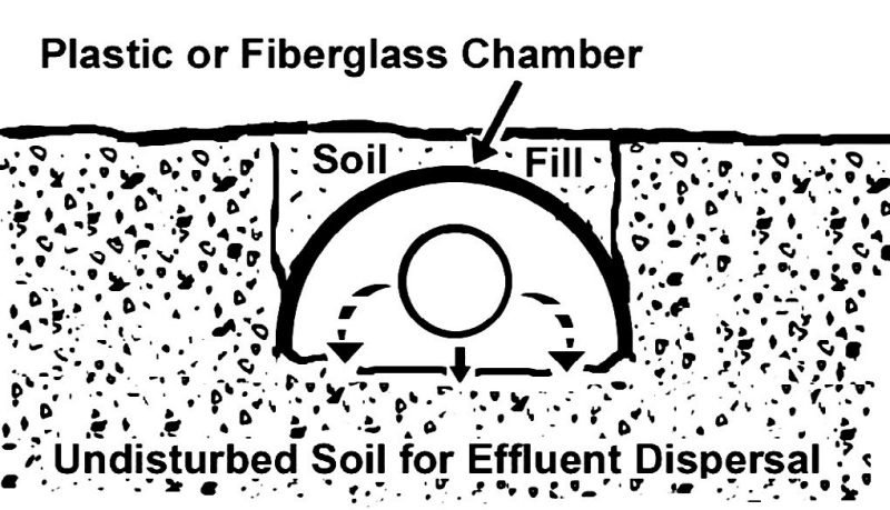
Soil Infiltration Chambers
Soil infiltration chambers are a newer absorption field design that uses semicylindrical PVC pipe in place of gravel-lined trenches (fig. 8). Each chamber is open at the bottom; chambers produced by various manufacturers have a variety of sidewall configurations. These systems can be made of materials that include plastic and fiberglass. Chambers minimize the introduction of soil into the leach system and, because gravel is not used, reduce the threat of drainfield compaction during construction. Chambers also offer ease of construction, especially in areas where gravel is difficult to obtain.
Shallow-Placed Systems
Under Virginia regulations, shallow-placed systems are defined as systems placed within 18 inches of the surface. Under Virginia regulations, shallow-placed systems must receive secondary or better quality effluent (VDH 2014).
Timed-dosage systems are usually used with shallow- placed systems, and in Virginia they are required where the system is within 12 inches of the surface. A timed-dosage system requires a pump. The pump chamber usually contains a storage volume, generally on the order of one day’s usage. Because effluent waters can be stored, the dispersal system can operate on an occasional basis, either at defined time periods or when a predefined volume of effluent accumulates in the pump chamber. This allows the absorption field to rest between effluent applications. The pump chamber is also capable of storing a volume of effluent in the event of a pump or power failure. Technologies for use in shallow-placed systems are reviewed below.
Low-Pressure Distribution
Low-pressure distribution system operation is similar to a conventional in-ground system, but there are several important differences.
One difference is the manner in which effluent is distributed through the dispersal system. Rather than relying on gravity, LPD systems are designed to ensure that effluent is distributed evenly to all areas of the soil absorption field. Effluent is directed to a collection chamber housing a pump that feeds the distribution lines, usually on a timed-dose basis.
The soil absorption field is constructed as shallow trenches that are usually gravel-lined (fig. 9). A network of PVC pipe, cemented with PVC glue so the joints can withstand pressure, is placed in the top of each trench. A series of small-diameter holes (usually in the range of 1/8-1/4 inch with individual diameters determined by engineering calculations) is drilled into the distribution pipes to allow effluent to move from the distribution lines to the trenches when the lines are pressurized by the pump.
One advantage of the LPD system, compared to a conventional septic system, is that the LPD requires less soil volume. Because the LPD system is designed for effective operation, it is much more likely to distribute effluent evenly over the entire drainfield, thus minimizing the potential for any area of the field to receive preferential flows. Thus, the LPD system can be constructed on a smaller area than a conventional septic field, and/or on soils with moderate limitations to wastewater treatment. LPDs are most commonly used as shallow-placed systems to receive secondary effluent. They can also be used in conjunction with a septic tank and filter to treat primary effluent if there is sufficient soil depth and area. LPD systems are used most often to disperse effluent from alternative secondary treatment devices, such as media filters, in areas where soil conditions limit conventional gravity dispersal.
An LPD system is more complex than a conventional septic system. Because pumps and control systems have limited lifetimes, LPD systems require more maintenance than conventional septic systems. More information on LPD systems is available from the National Small Flows Clearinghouse (use search tool at https://www.nesc.wvu.edu/topics-of-interest).
Filtration Beds
Filtration beds (also called “filter beds”) are constructed above the land surface to distribute effluent across an area of natural soil for infiltration. A common filter bed could be 1-2 feet in depth and rectangular in shape, constructed of sand and gravel above the soil surface. A gravel layer at the top of the filter bed aids the distribution of effluent across a sand layer. The effluent percolates through the sand layer to the soil below. A filter bed may be used in an area of shallow bedrock or high groundwater, where the groundwater does not come to the surface.
Filter beds can receive effluent from any secondary treatment device. They are used most commonly, however, to disperse effluent produced by modular units such as peat-based treatment systems (fig. 10). Peat systems, for example, can be placed directly above a filter bed, allowing secondary effluent to move from the secondary treatment into the filter bed by gravity. Because the gravel matrix offers little resistance to lateral flow, the effluent is dispersed over the treatment area and soaks into the soil below. The filter bed is usually covered with earth and vegetated.
The advantages of filter beds are that they are low-cost and easy to construct. It is essential that the soil below the filter bed be permeable and level so that gravity does not cause the effluent to collect preferentially in one area. The area intended for filter bed construction should be prepared by removing the vegetation and leveling precisely. The area should not be compacted with equipment; in fact, the area should be loosened after leveling to assure that effluent is able to percolate downward. Filter beds can be built in areas of shallow depth to groundwater or shallow depth to rock because they are built at the ground surface and do not require excavation. However, at least some unsaturated soil must remain in place between the filter bed base and either bedrock or seasonal high water tables.
Trickle Irrigation
Another means of distributing effluent to soils is trickle or drip irrigation (fig. 11). A trickle irrigation system is built from narrow-diameter tubing with small holes in the side walls. Tubing manufactured for this purpose can be purchased by an installation contractor from an equipment dealer. The tubing system is built to withstand internal pressure. These tubes are buried just a few inches, at most, below the ground surface. A pump distributes effluent to the trickle irrigation tubing through which it is dispersed into the soil. The system is engineered to ensure even distribution of effluent over the entire tubing network.
When properly installed and operated, trickle irrigation is a highly effective subsurface effluent dispersal system because the quantity of effluent applied in each dose can be accurately controlled. This combination of factors allows the system designer to solve problems that can’t be readily addressed with other subsurface dispersal methods. It is essential that all particulate contaminants be filtered from effluent intended for drip irrigation in order to prevent clogging of distribution holes. For this reason, drip irrigation systems normally are outfitted with a small-diameter filter to remove additional particulates from the secondary effluent. The systems are also constructed with a backflow-flush cycle that reverses the fluid flow direction in the tubing periodically to remove any small particles that may have passed through the filter and become lodged in the tubing network. Trickle irrigation systems should be constructed in areas that are not subjected to regular foot or vehicular traffic.
Originally, these systems were constructed from piping supplied to agricultural irrigators. Recently, however, some manufacturers have begun producing piping designed specifically for use in effluent dispersal.
Contour Systems
Typically, a subsurface effluent disposal system (also called a “trench” or “bed-type” drain field) is installed at a constant depth from the ground surface along a contour, at a constant elevation. The contour system is best suited to sites with sloping ground. The system is placed at a constant depth across the slope and laid out so the trench bottom is level throughout its entire length. These are typically called contour systems because the installation of a level trench bottom at a constant depth requires that it follow what would be a constant-elevation contour line on a topographic map. A contour system is expected to distribute the effluent uniformly in the soil, thus avoiding undesired surfacing or breakout of the effluent on the ground surface.
The contour system can be designed to disperse effluent below the surface using either gravity or pressurized flow (low pressure or drip) with gravel-lined trenches, infiltration chambers, or other nongravel trench methods. Because soil limitations are common on sloping sites, most contour systems are designed to use pressurized flow. On sites where installation of a true contour system is not practical or possible, a technology such as a drip system may be used to install the system at a relatively constant or variable depth below the surface but not along the true contour of the ground surface.
As with all subsurface effluent dispersal systems, developers of contour systems should consider a linear hydraulic loading rate (gallons of effluent applied per day, per foot of trench) in the design. A number of soil- and site-related parameters (including soil conductivity, slope, and other characteristics) influence the allowable linear hydraulic loading rate; a system designer can determine an appropriate value of the linear hydraulic loading rate based on soil and site conditions observed on the site. Systems built on sloping ground are prone to the emergence of effluent at the surface if the system is not sized and sited adequately.
Although not commonly allowed by most regulations, it is possible to install a subsurface effluent dispersal system at a variable depth below ground surface on sites with slope such that the bottom of the trench, bed, or drip line is level (at a constant elevation). From a theoretical viewpoint, the effluent dispersal system installed at a variable depth below ground surface, not along the ground contour, can be designed to operate in a manner similar to a true contour system installed at a constant depth. Although such an application can take advantage of site characteristics to overcome soil and other limitations, it does require care and attention to detail in the design and construction.
Surface Discharge Systems
Discharge of tertiary effluent above the surface is allowed in certain situations (VDH 2014). Spray irrigation and discharge into streams are the two main disposal methods; they require advanced techniques and equipment to conduct advanced treatment, and they sometimes require disinfection before discharge is allowed.
Spray Irrigation
Spray irrigation is a means of dispersing treated effluent on the land surface (fig. 12). Spray irrigation systems work in a manner similar to a small lawn sprinkler, spraying effluent uniformly over a land surface area. Spray systems are commonly linked to a storage chamber and timed to distribute effluent in a controlled manner when human exposure is likely to be minimized, such as late night. By regulation, effluent must be disinfected prior to being dispersed via spray irrigation, and spray irrigation systems must be located beyond specified distances from occupied homes.
Surface-Water Discharge
This option refers to discharge to a stream, pond, or other surface water. Water discharged to surface water must meet water quality standards. Operators of surface water discharge systems must monitor system operations by taking and analyzing at least one sample per year for BOD and suspended solids. All effluent from surface discharge systems (both surface water discharge and spray irrigation) must be disinfected prior to release. All surface discharge systems must receive an alternative discharge permit as well as an on-site wastewater disposal permit (VDH 2014).
Summary
A variety of alternatives to conventional on-site wastewater systems are available. These systems are more expensive and require more frequent attention and maintenance than conventional systems, and they typically require electric power. Thus, their use is generally confined to situations where public sewers are not available and site conditions are not suitable for conventional on-site systems. They do, however, provide safe and effective wastewater treatment when properly installed and maintained.
Property owners with a desire to install alternative on-site wastewater treatment systems are advised to educate themselves about the various systems that are available, obtain the services of a competent and reliable contractor to install the system, consult with the local health department personnel, and assure that all necessary permits are obtained. State regulations governing alternative systems are subject to change, so readers planning alternative systems should verify that the regulatory requirements discussed in this publication remain in effect (www.vdh.virginia.gov/ EnvironmentalHealth/Onsite/regulations/).
Installed systems must be maintained on a regular basis. Homeowners with such systems are advised to establish a maintenance contract with a qualified contractor.
Acknowledgements
The authors thank George Wills of Blacksburg, Virginia, for the illustrations and Anish Jantrania, former technical services engineer, Virginia Department of Health, for contributions to this publication. We also thank our reviewers for their helpful comments.
Contact the Authors
J.M. Galbraith john.galbraith@vt.edu
P.J. Brown 540-231-1431
Please return comments to:
John Galbraith
Crop and Soil Environmental Sciences (0404) 239 Smyth Hall, Virginia Tech
185 Ag Quad Lane Blacksburg, VA 24061
References
Brown, P., and S. Thomas. 2022. Septic System Best Management Practices. Virginia Cooperative Extension publication SPES-380P. https://www.pubs.ext.vt.edu/SPES/spes-380/spes-380.html
Brown, P., and S. Thomas. 2022. What Happens If My Septic System Fails?. Virginia Cooperative Extension publication SPES-379P. https://www.pubs.ext.vt.edu/SPES/spes-380/spes-380.html.
Hoover, M., and T. Konsler. 2004. Soil Facts: Septic Systems and Their Maintenance. North Carolina Cooperative Extension publication AG-439-13. https://content.ces.ncsu.edu/show_ep3_pdf/1692550853/23229/.
Hoover, M. 2004. Septic System Owner’s Guide. North Carolina Cooperative Extension publication AG-439-22. https://content.ces.ncsu.edu/ show_ep3_pdf/1692550810/23228/.
Reneau, R. B., C. Hagedorn, and M. J. Degen. 1989. “Fate and Transport of Biological and Inorganic Contaminants from On-Site Disposal of Domestic Wastewater.” Journal of Environmental Quality 18:135-44. https://doi.org/10.2134/jeq1989.00472425001800020001x.
U.S. Census Bureau. 2013. American Housing Survey for the United States: 2011. Washington, D.C.: U.S. Government Printing Office. https://www.census.gov/content/dam/Census/library/publications/2013/ demo/h150-11.pdf.
U.S. Census Bureau. 2022. American Housing Survey for the United States: 2021. Washington, D.C.: U.S. Government Printing Office. https://www.epa.gov/system/files/documents/2022-01/low-mod-income- without-treatment_report-to-congress.pdf.
U.S. EPA (U.S. Environmental Protection Agency). 2002. Onsite Wastewater Treatment Systems Manual. Office of Water. EPA publication EPA/625/R-00/008. https://www.epa.gov/sites/ default/files/2015-06/documents/2004_07_07_ septics_septic_2002_osdm_all.pdf.
U.S. EPA (U.S. Environmental Protection Agency). 2003. Voluntary National Guidelines for Management of Onsite and Clustered (Decentralized) Wastewater Treatment Systems. Office of Water Office of Research and Development EPA publication EPA 832-B-03-001. https://www.epa.gov/sites/default/files/2015-06/documents/septic_guidelines.pdf.
VDH (Virginia Department of Health). 2011. Regulations For Alternative Onsite Sewage Systems. 12 VAC 5-613-10 et seq. Richmond: VDH. https:// www.vdh.virginia.gov/EnvironmentalHealth/ONSITE/regulations/documents/2012/pdf/12 VAC 5 613.pdf.
VDH (Virginia Department of Health). 2014. Sewage Handling and Disposal Regulations (Emergency Regulations for Gravelless Material and Drip Dispersal). 12 VAC 5-610-10 et seq. Richmond: VDH. https://www.vdh.virginia.gov/EnvironmentalHealth/ONSITE/regulations/ documents/2012/pdf/12 VAC 5 610.pdf.
Virginia Cooperative Extension materials are available for public use, reprint, or citation without further permission, provided the use includes credit to the author and to Virginia Cooperative Extension, Virginia Tech, and Virginia State University.
Virginia Cooperative Extension is a partnership of Virginia Tech, Virginia State University, the U.S. Department of Agriculture (USDA), and local governments, and is an equal opportunity employer. For the full non-discrimination statement, please visit ext.vt.edu/accessibility.
Publication Date
October 19, 2023